Model
R
at
ed S
to
ra
ge
C
ap
ac
it
y, G
A
L (
L)
R
at
ed M
ax
im
u
m
In
p
ut
, B
tu
/h
r (
kW
)
T
he
rm
al
E
ffi
ci
enc
y
(%
) @ M
ax
. I
n
p
ut
R
ec
ov
er
y @ 1
00
°F
ri
se, G
A
L/
H
R (
L/
H
R
)
A
C
E
G
HO
T
(
N
P
T
)
R
at
ed M
in
im
u
m
In
p
ut
, B
tu
/h
r (
kW
)
T
he
rm
al
E
ffi
ci
enc
y
(%
) @ M
in
. I
n
p
ut
1s
t H
r. D
el
iv
er
y @
10
0°
F r
is
e, G
A
L (
L)
B
D
F
C
OL
D
(
N
P
T
)
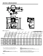
Table 1: Dimensions
Page 4
SECTION I: SPECIFICATIONS
Figure 1: All Models
DIMENSIONS, INCHES (cm)
NOTE: * denotes fuel type, N or LP, and suffix “-A” denotes ASME
For HIGH ALTITUDE models, the following additional suffixes are defined as:
“-H28” = Approved for altitudes greater than 2,000 up to 7,800 FT
For natural gas:
MINIMUM GAS SUPPLY PRESSURE
(at gas control) = 4.0” W.C. (dynamic)
MAXIMUM GAS SUPPLY PRESSURE
(at gas control) = 14” W.C. (static or dynamic)
A
ir I
n
ta
ke (
P
V
C
)
G
as (
N
P
T
)
E
x
h
au
st
Ve
n
t (
P
V
C
)
Sh
ip
p
in
g W
ei
gh
t,
L
B
S (
kg
)
For LP gas:
MINIMUM GAS SUPPLY PRESSURE
(at gas control) = 8” W.C. (dynamic)
MAXIMUM GAS SUPPLY PRESSURE
(at gas control) = 14” W.C. (static or dynamic)
Note: Dynamic pressure is measured while gas is flowing and static pressure is measured while gas is
not flowing.
All Bock products meet or exceed current ASHRAE standards.
These products are design certified by UL (Underwriters Laboratories) and meet ANSI Z21.10.3/CSA 4.3
requirements for operation up to 180°F (82°C) as a Category IV water heater.
Approved for use as a direct vent automatic instantaneous water heater.
R
EC
IR
C
U
L
A
T
IO
N
RE
T
U
RN
(
N
P
T)
CONNECTION SIZES
H
OT600*-A
130
(492)
600,000
(175)
140,000
(41)
98
99
706
(2,675)
797
(3,017)
78
(199)
34
(86)
68
(173)
15
(38)
13
(33)
67
(170)
78
(198)
42
(106)
80
(203)
83
(211)
2”
2”
1”
2”
6”
6”
1,700
(773)
OT700*-A
700,000
(205)
98
824
(3,121)
915
(3,464)
OT800*-A
800,000
(235)
98
941
(3,567)
1,032
(3,907)
OT900*-A
900,000
(264)
98
1,059
(4,013)
1,150
(4,353)
I
J
Содержание OT600-A
Страница 35: ...SECTION IV INSTALLATION Page 35 Figure 26 Piping Diagram One Unit Figure 27 Piping Diagram Two Units ...
Страница 40: ...Page 40 SECTION IV INSTALLATION Figure 32 Component Wiring Diagram ...
Страница 41: ...Page 41 Figure 33 Schematic Wiring Diagram SECTION IV INSTALLATION ...
Страница 62: ...Page 62 ...


