Page 19
SECTION IV: INSTALLATION
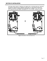
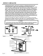
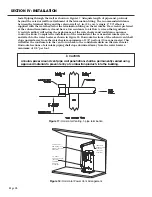
Determine which direction minimizes the length of the condensate drain line, and point
the orienter in that direction. Install the trap portion by connecting the union parts
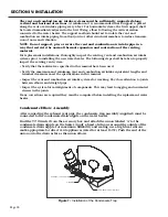
labeled ‘B’ so that it is pointing in the proper direction. See Figure 7 for a view of how
the condensate trap is assembled, and Figure 8 for a view of both orientation options.
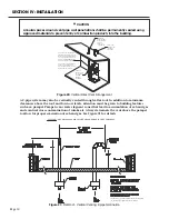
Figure 8:
Orientation of the Condensate Trap
Содержание OT600-A
Страница 35: ...SECTION IV INSTALLATION Page 35 Figure 26 Piping Diagram One Unit Figure 27 Piping Diagram Two Units ...
Страница 40: ...Page 40 SECTION IV INSTALLATION Figure 32 Component Wiring Diagram ...
Страница 41: ...Page 41 Figure 33 Schematic Wiring Diagram SECTION IV INSTALLATION ...
Страница 62: ...Page 62 ...

