Page 46
SECTION VI: MAINTENANCE
NOTICE TO THE OWNER:
If you are having a mechanical problem with your water
heater, contact your service company or installer.
The required maintenance schedule for this water heater is shown in Table 7. Further detail is
given in this section for each component.
WATER PIPING
On an annual basis, all piping should be checked for leakage at joints, shut-off valves, and
unions.
T&P RELIEF VALVE
On an annual basis, the temperature and pressure relief valve should be checked for proper
operation. First, attach a drain line to the valve to direct the water discharge to an open drain.
This is very important because the temperature of the discharge could be very hot. Second,
lift lever at the end of the valve several times. The valve should operate freely and return to
its original position properly. If water does not flow out of the valve, remove and inspect for
corrosion or obstructions. Replace with a new valve if necessary. Do not repair the faulty valve
as this may cause improper operation.
ANODE RODS
The water heater is supplied with a factory installed powered anode system to prevent corrosion
of internal tank components. The anode rods in the tank are made from titanium and are not
consumed over time and, therefore, do not need to be removed and inspected.
The powered anode module is mounted on the control panel underneath the control enclosure
cover. The status LED is located adjacent to the display. When the tank is filled with water and
the heater is connected to the power supply, the status LED will be green. If the LED is flashing
red, this indicates a system error. Refer to Table 11 in Section VII: Troubleshooting
for possible causes and remedies when the LED is flashing red. Check the status LED every
three months to ensure proper operation.
NOTICE TO THE OWNER:
The water heater must be connected to the power supply for
the powered anode system to operate. DO NOT DISCONNECT THE WATER HEATER FROM
THE POWER SUPPLY FOR AN EXTENDED PERIOD OF TIME. WITHOUT POWER, THE ANODE
SYSTEM WILL NOT BE CAPABLE OF PROVIDING CORROSION PROTECTION. When the power
switch to the right of the display is OFF and there is a connection to the power supply, the
powered anode system will still function. If the water heater must be disconnected from
the power supply for an extended period, the tank must be drained. Refill the tank prior to
reconnecting the water heater to the power supply.
Table 7: Maintenance Schedule
Component
Operation
Interval
Required
Water piping
Check for leaks
Annually
Repair when necessary
T&P Relief Valve
Verify operation
Annually
Proper operation
Powered Anode System
Check status LED
3 months
Verify “green” LED status
Tank
Sediment removal
6 months
Flush tank
Vent System
Inspect
Annually
Terminations are clear; vent screens are
clean; joints are sealed; proper support
Condensate Neutralizer
Replace Media
Annually
Replace neutralizing media
Condensate Trap
Inspect
6 months
Remove sediment
Combustion System
Measurements
Annually
Check inlet gas pressure; take
combustion reading (O2%)
Low Water Cutoff
(optional component)
Verify operation
Annually
Low Water Error properly generated
Содержание OT600-A
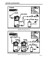
Страница 35: ...SECTION IV INSTALLATION Page 35 Figure 26 Piping Diagram One Unit Figure 27 Piping Diagram Two Units ...
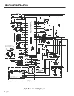
Страница 40: ...Page 40 SECTION IV INSTALLATION Figure 32 Component Wiring Diagram ...
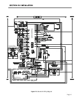
Страница 41: ...Page 41 Figure 33 Schematic Wiring Diagram SECTION IV INSTALLATION ...
Страница 62: ...Page 62 ...

