


SECTION III: PRE-INSTALLATION
GAS SUPPLY LINE
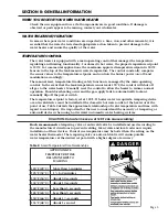
Prior to installation, contact your local gas utility to confirm that sufficient gas service is available
for the water heater. The gas meter must have adequate capacity to supply the rated maximum gas
input of the water heater in addition to other gas fired equipment connected to the meter.
Minimum Gas Supply Pressure
The gas supply must be capable of maintaining a minimum pressure at the inlet of the gas control
during water heater operation at maximum input. The pressure will be lowest at the gas control
during water heater operation (i.e. gas is flowing) at maximum input. For natural gas models,
during operation at maximum input, the supply pressure at the gas control must be at least 4.0”
W.C. For LP gas models, during operation at maximum input, the supply pressure at the gas
control must be at least 8” W.C.
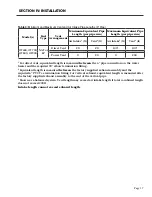
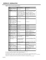
Refer to Table 3 for gas supply line sizing. The table shows maximum input in thousands of BTU’s
per hour for various pipe sizes and lengths. The table assumes gas supply pressures of 14” W.C. or
less and a pressure drop of 0.3” W.C.
At minimum, use 1-1/2” gas supply pipe for model OT600.
For models OT700-900, use a minimum of 2” pipe.
Maximum Gas Supply Pressure
The gas supply pressure shall never be greater than 14” W.C.
Refer to Section IV: Installation / Gas Connections for further installation instructions.
Page 12
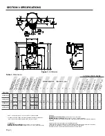
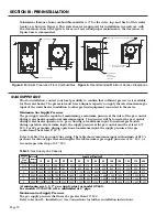
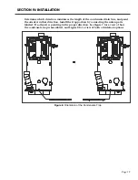
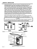
Figure 4:
Minimum Clearance From Combustibles Figure 5: Recommended Minimum Access Clearances
Nominal
Iron Pipe
Size
(inches)
Internal
Diameter
(inches)
Length of Pipe (feet)
10
20
30
40
50
60
70
80
90
100
125
150
175
200
1 1/4
1.380
1,050
730
590
500
440
400
370
350
320
305
275
250
225
210
1 1/2
1.610
1,600 1,100
890
760
670
610
560
530
490
460
410
380
350
320
2
2.067
3,050 2,100
1,650
1,450
1,270
1,150
1,050
990
930
870
780
710
650
610
2 1/2
2.469
4,800 3,300
2,700
2,300
2,000
1,850
1,700
1,600
1,500
1,400
1,250
1,130
1,050
980
3
3.068
8,500 5,900
4,700
4,100
3,600
3,250
3,000
2,800
2,600
2,500
2,200
2,000
1,850
1,700
4
4.026 17,500 12,000 9,700
8,300
7,400
6,800
6,200
5,800
5,400
5,100
4,500
4,100
3,800
3,500
Table 3: Gas Supply Line Capacity
0"
COMBUSTIBLE FLOORING
0"
0"
0"
SECTION B-B
6in
0in
0in
SECTION N-N
COMBUSTIBLE WALLS
24"
8"
12"
COMBUSTIBLE OR NON-COMBUSTIBLE WALLS
COMBUSTIBLE
OR NON-
COMBUSTIBLE
FLOORING
24" FOR ACCESS IN FRONT
OF WATER HEATER
0
SECTION C-C
Minimum clearance from combustible material is 0” for the sides, top, and back of this water
heater, as shown in Figure 4. This water heater is approved for installation in an alcove with
the clearances shown in Figure 4.
For ease of access and proper maintenance, the clearances in
Figure 5 are recommended.
Содержание OT600-A
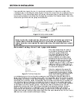
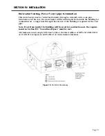
Страница 35: ...SECTION IV INSTALLATION Page 35 Figure 26 Piping Diagram One Unit Figure 27 Piping Diagram Two Units ...
Страница 40: ...Page 40 SECTION IV INSTALLATION Figure 32 Component Wiring Diagram ...
Страница 41: ...Page 41 Figure 33 Schematic Wiring Diagram SECTION IV INSTALLATION ...
Страница 62: ...Page 62 ...


