Page 16
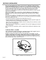
NOTE: The equivalent straight pipe length of a 90°, 1/4 standard bend elbow and
a 45°, 1/8 standard bend elbow is 5 feet and 2.5 feet, respectively. DO NOT use
short bend elbows.
NOTE: An elbow used as an exhaust vent termination fitting must be included
when determining the total number of elbows.
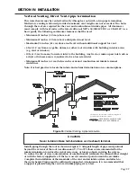
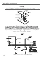
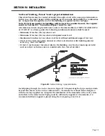
Figure 6:
Establishing the Intake and Exhaust Vents
SECTION IV: INSTALLATION
Minimum and Maximum System Lengths
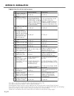
The water heater should be located such that plastic vent pipe lengths and the number
of connection fittings are minimized. Minimum and maximum equivalent pipe lengths
for the vent and combustion air intake systems are given in Table 4. 6” diameter piping
must be used. The water heater is provided with a 6” female PVC connection for the air
intake and a 6” female PVC connection for the exhaust vent. For ease of installation and
potential future inspection, a 4” flexible coupling is used as the first connection on the
blower.
DO NOT use less than 6” diameter plastic pipe and DO NOT use unequal sizes except as
shown to increase from 4” to 6” diameter at the point of connection to the water heater.
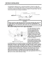
Figure 6 shows the proper connections to increase from 4” to 6” plastic pipe on the
intake, and how to establish the exhaust venting with the factory supplied assembly.
Prior to connecting the exhaust assembly, apply a bead of silicone around the inside of
the straight coupling. For maximum durability and sealing, use a high heat silicone caulk
for direct vent appliances (rated for at least 150°F). Apply a bead around the end of the
exhaust pipe as well. Push the end of the coupling over the exhaust pipe as far as the pipe
allows.
P
DETAIL P
SCALE 1 : 16
EXHAUST ASSEMBLY
(FACTORY SUPPLIED)
APPLY BEAD HIGH TEMP
SILICON CAULK ALL THE
WAY AROUND PRIOR TO
PUSHING ON THE
EXHAUST ASSEMBLY.
G
DETAIL G
SCALE 1 : 16
4" X 6" INCREASER
(FACTORY SUPPLIED)
4" FLEXIBLE COUPLING
(FACTORY SUPPLIED"
AIR INTAKE
H
M
DETAIL H
SCALE 1 : 16
6" 22.5° ELBOW
(FACTORY SUPPLIED)
6" PVC STRAIGHT COUPLING
(FACTORY SUPPLIED)
6" STRAIGHT PIPE
(FACTORY SUPPLIED)
K
DETAIL K
SCALE 1 : 16
SEAL WITH
SILICONE CAULK
ALL THE WAY
AROUND
CONNECTION.
SEAL
CONNECTION
WITH PVC PRIMER
AND CEMENT.
DETAIL M
SCALE 1 : 16
EXHAUST PIPE ELBOW
UNION 'B'
3/4" FEMALE NPT
EXHAUST VENT
EXHAUST VENT
)
Содержание OT600-A
Страница 35: ...SECTION IV INSTALLATION Page 35 Figure 26 Piping Diagram One Unit Figure 27 Piping Diagram Two Units ...
Страница 40: ...Page 40 SECTION IV INSTALLATION Figure 32 Component Wiring Diagram ...
Страница 41: ...Page 41 Figure 33 Schematic Wiring Diagram SECTION IV INSTALLATION ...
Страница 62: ...Page 62 ...

