SECTION IV: INSTALLATION
Page 21
DANGER
Failure to prime the condensate trap with water will result in combustion gas (which may
contain carbon monoxide) entering the room. To avoid the risk of asphyxiation from
carbon monoxide, never operate the water heater unless the condensate trap is sealed
with water.
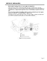
Horizontal Venting, Direct Vent 2-pipe termination
This water heater may be vented
horizontally (through a sidewall)
with a two-pipe termination.
Two holes through an exterior
wall are required for the vent
and combustion air intake pipes.
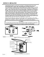
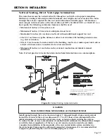
Minimum clearances between the
terminals must be met as specified
in Figure 14. All clearances must
comply with local codes or the latest
edition of NFPA 54/ANSI Z223.1 or
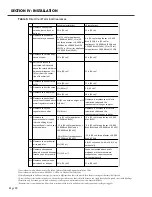
CSA B149. See Figure 13 and Table 5
for terminal clearances.
Check to make sure flue gases DO
NOT recirculate into the air intake
terminal when using direct venting.
If the water heater is having service
issues, flue recircula tion may be
a contributing factor. Even when the minimum vent terminal separation distances in
Figure 14 are followed, recirculation may still occur depend ing upon the location outside
the building, the distance from other buildings, proximity to cor ners, weather conditions,
wind patterns, and snow depth. Periodically check to make sure that flue recirculation is
not occurring. Signs of flue gas recirculation include frosted or frozen intake terminals,
condensate in the intake terminal and venting system, oxidation or white chalk material
on the flame rod or hot surface igniter. Correction to flue recirculation may involve
angling the in take away from the exhaust terminal, increasing the distance between
them, or using inside air for combustion. Check to be sure the intake and ex haust
terminals are not obstructed, especially dur ing periods of below freezing weather. All
intake and exhaust venting components must have the same diameter size. DO NOT use a
different size on the intake and exhaust venting.
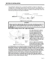
Some installations require the use of a condensate neutralizer to reduce the acidity of the
condensate prior to reaching the drain. Figure 12 shows the connection of a condensate line to
a neutralizer. It is recommended that a low profile condensate pump is installed between the
heater and neutralizer to facilitate flow through the neutralizer. For further details, refer to the
instructions provided with the pump and neutralizer.
Figure 12: Pump and Neutralizer
Figure 13:
Terminal Clearances
Содержание OT600-A
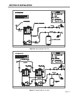
Страница 35: ...SECTION IV INSTALLATION Page 35 Figure 26 Piping Diagram One Unit Figure 27 Piping Diagram Two Units ...
Страница 40: ...Page 40 SECTION IV INSTALLATION Figure 32 Component Wiring Diagram ...
Страница 41: ...Page 41 Figure 33 Schematic Wiring Diagram SECTION IV INSTALLATION ...
Страница 62: ...Page 62 ...


