Page 38
SECTION IV: INSTALLATION
GAS CONNECTIONS
CAUTION
Do not use this water heater with any gas other than the type listed on the rating label.
Check the rating label on the front of the water heater and make sure the gas to be
used matches the gas stated on the rating label. Consult your local gas company or
Bock Water Heaters with any questions.
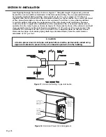
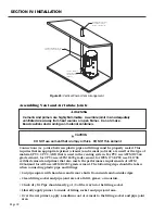
A manual valve, union, and a
sediment trap shall be provided
in front of the gas valve. All gas
piping must conform to local
codes and/or the National Fuel
Gas Code ANSI 223.1/NFPA 54
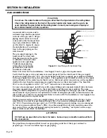
or CSA B149.1. Figure 31 shows
the installation of a sediment
trap to the gas piping on the
water heater.
The gas supply piping to the
heater must be sized such
that the pressure at the valve
is sufficient when all other
appliances are operating.
Undersized gas piping
will reduce water heater
performance and result
in nuisance lockouts.
Refer to Section III: Pre-Installation / Gas Supply Line for pipe size requirements.
Verify that the gas service and meter are sized properly for the total load. If the gas supply
pressure is greater than 14” W.C., the water heater must have a supply gas regulator installed
in the gas supply line for each water heater. The regulator must be rated at or above the input
rating (Btu/hr) of the water heater that it serves. Inlet and outlet connections on the regulator
shall not be less than the minimum gas supply line size for the water heater. The Maxitrol
325-7 series of regulators with 1-1/2” or 2” connections is recommended.
For ease of measurement, install a tee with a pipe fitting and a manual shutoff valve between
the main manual shut-off valve to the water heater and the pressure regulator. The pipe
fitting should be adaptable to a pressure gauge for measuring incoming gas pressure. If further
measurement of gas pressure is required due to lack of adequate pressure, measurement at the
inlet of the gas control is recommended. Refer to Section III: Pre-Installation / Gas Supply Line
for minimum pressure requirements.
During pressure testing of the gas supply piping, close the manual gas shut-off valve to the
water heater to avoid over pressuring the gas valve. Test pressure shall
not exceed
1
⁄
2
PSIG
(14” W.C). Pressurizing the gas valve over 1/2 PSIG during pressure testing is not recommend.
To test at a pressure greater than
1
⁄
2
PSIG, close the manual shut-off valve and disconnect the
gas control. Turn on gas and inspect piping for leaks by “painting” each joint with a soapy
water solution and check for bubbles.
WARNING
DO NOT use an open flame to check for leaks. Serious injury or death could result from
fire or explosion.
The pipe thread compound that is used on gas piping must be of the type resistant to
propane gas. Do not use teflon tape on gas piping.
L
DETAIL L
SCALE 1 : 10
SEDIMENT TRAP
PIPE CAP
TEE
UNION
MAIN GAS SHUTOFF VALVE
REGULATED GAS SUPPLY LINE
Figure 31: Gas Piping with Sediment Trap
Содержание OT600-A
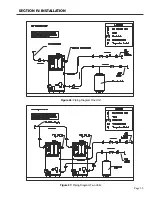
Страница 35: ...SECTION IV INSTALLATION Page 35 Figure 26 Piping Diagram One Unit Figure 27 Piping Diagram Two Units ...
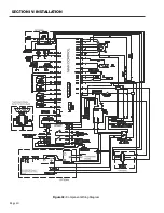
Страница 40: ...Page 40 SECTION IV INSTALLATION Figure 32 Component Wiring Diagram ...
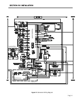
Страница 41: ...Page 41 Figure 33 Schematic Wiring Diagram SECTION IV INSTALLATION ...
Страница 62: ...Page 62 ...

