


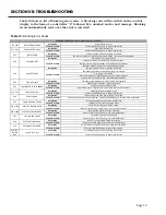


SECTION VII: TROUBLESHOOTING
USING THE DISPLAY
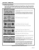
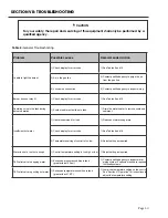
System and troubleshooting information such as fan speeds, flame signal, ignition attempts,
and error history is available from the display. Refer to Figure 39 (below) for instructions to
access this information and understanding the display.
Page 54
The Home screen displays valuable information for the given state
of the water heater (standby, demand, or error).
When in demand, the power bar shows the magnitude of the fan speed
within the factory set rate. When the blower, gas, and flame icons are
on, the power bar is synonymous with burner power (100% is Max
Power and 1% is Min Power). If only the blower icon is on, then the
power bar represents pre-purge or post-purge operation. The bolt icon
represents ignitor operation.
The flame signal meter will be green if the magnitude of the current
is acceptable.
If the heater is in error, the type of error, error code, and description
are displayed on the Home screen.
The Status screen contains useful, real-time information pertaining
to fan speeds and sensor values.
The History screen contains useful, real-time information about burner
run time, successful and failed ignitions, and flame failures.
It also gives the option to view blocking and lockout error logs.
The blocking error log displays the history of blocking errors (“E” codes).
The most recent error is shown first with the date and time displayed.
Use the scroll bar to view the error history.
With a USB stick connected, press the USB save icon to export this log.
Press the <<< button to go to the previous screen.
The lockout error log displays the history of lockout errors (“A” codes).
The most recent error is shown first with the date and time displayed.
With a USB stick connected, press the USB save icon to export this log.
Figure 39: Using the Display
Содержание OT600-A
Страница 35: ...SECTION IV INSTALLATION Page 35 Figure 26 Piping Diagram One Unit Figure 27 Piping Diagram Two Units ...
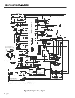
Страница 40: ...Page 40 SECTION IV INSTALLATION Figure 32 Component Wiring Diagram ...
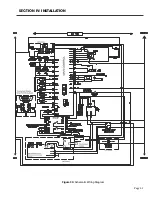
Страница 41: ...Page 41 Figure 33 Schematic Wiring Diagram SECTION IV INSTALLATION ...
Страница 62: ...Page 62 ...


