


Page 31
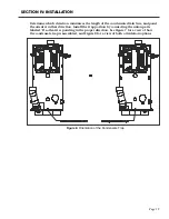
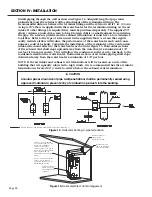
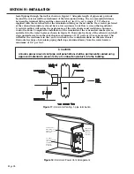
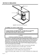
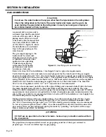
Install piping through the roof as shown in Figure 22. Adequate length of pipe must protrude
beyond the exterior of the roof (see dimension Y). Terminate the exhaust either straight or
with the factory supplied tee. Complete the installation of the remainder of the vent system
and attach to the water heater. Piping must be sufficiently supported. At minimum, it is
recommended that a support is placed along the vent piping every 4 feet.
SECTION IV: INSTALLATION
* Exhaust may be terminated with factory supplied tee.
Tee must not point towards air intake.
Figure 22: Vertical Venting, 1-pipe termination
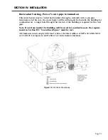
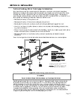
Vertical Venting, Power Vent 1-pipe termination
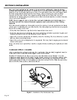
This water heater may be vented vertically (through a roof) with a one-pipe termination.
In this case, the water heater will be utilizing air from inside the building for combustion
air. A single hole through the roof of the building is required for the vent pipe.
Note: If air from inside the building will be used for combustion air, the require-
ments in Section III, “Unconfined Space” must be met.
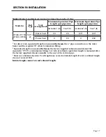
All clearances must comply with local codes or the latest edition of NFPA 54/ANSI Z223.1
or CSA B149. As a basic guide, the following minimum clearances shall be used:
• Minimum 12 inches (30 cm) above roof.
• Minimum 12 inches (30 cm) above anticipated snow level.
• Maximum 24 inches (61 cm) above roof level without additional support for vent.
• 4 feet (1.2 m) from any gable, dormer or other roof structure with building interior
access (e.g. vent or window).
• 10 feet (3 m) from any forced air inlet to the building. Any fresh or make-up air inlet
such as a dryer or furnace area is considered to be a forced air inlet.
Содержание OT600-A
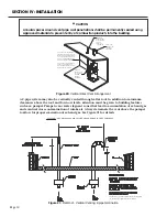
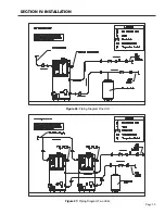
Страница 35: ...SECTION IV INSTALLATION Page 35 Figure 26 Piping Diagram One Unit Figure 27 Piping Diagram Two Units ...
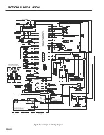
Страница 40: ...Page 40 SECTION IV INSTALLATION Figure 32 Component Wiring Diagram ...
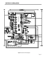
Страница 41: ...Page 41 Figure 33 Schematic Wiring Diagram SECTION IV INSTALLATION ...
Страница 62: ...Page 62 ...


