


Page 56
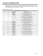
SECTION VIII: PARTS LIST
5
7
9
8
14
4
6
4
8
22
21
4
33
4
20
12
9
16
17
1
2
3
31
25
23
24
28
29
30
11
10
13
19
9
26
27
32 26
15
PARTS NOT
BALLOONED
ARE SHOWN
IN THE
BURNER
ASSEMBLY
18
ITEM 14 SEE CONTROL PANEL PARTS FINDER.
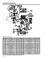
PARTS FINDER OT600-900*(-A): TANK
ITEM
NO.
DESCRIPTION
PART
NUMBER
1
Insulation, Tank Top
18229
2
Baffle, 2in
16604
3
Second Pass Transition
Cover
Contact
Bock
4 Pipe Nipple, 2" x 5" x 8-1/4",
PS CE
15407
5
Cover, Ctrl Pnl, Right
17123
6
Tasseron Duplex Sensor,
0.25NPT, Brass
21594
7
T&P valve, 1.5", FVX-4
21800
8 Anode, Magontec, 200mm 15151
9
Cap, Plastic, for 3" hole
17593
10
Hand Hole Gasket
15560
11
Cover Plate, 8"
17190
12
Drain Valve, 3/4in NPT
15590
13 Anode, Magontec, 500mm 15153
14
Control Panel Assembly
SEE NOTE
15
Spark Generator
19944
16
HB Fitting, 1/4"NPT x 1/4"
Hose Barb
17277
17 Tasseron Sensor, 0.25NPT,
SS
21596
18
Condensate Assembly
running trap.
19987
19
Cover, Exhaust, Right
19412
20
Cover, Exhaust, Left
19413
21
4.25in Cover Plate
17235
22
Cover, Ctrl Pnl, Left
17122
23 Burner Bracket Refractory
Disc
18008
24 Blower, Fasco, GPM 7.0-7H 19903
25 optiTHERM, Flame Rod, 4in
19853
26 #8-32 x 0.25in Socket Head
Cap Screw
25137
27 Gasket, optiTHERM Flame
Rod
18209
28
4in Rubber Coupling
20537
29
PVC Schedule 40 DWV
Pipe 4" DIA x 4" L
18249
30
Reducer, 4"-6", PVC
18248
31
Spark Igniter
19940
32
Gasket, Spark
17910
33
Exhaust Assembly
ITEM
NO.
DESCRIPTION
PART
NUMBER
36 Gasket, Blower-transtube,
OT600-900
17905
37
Sensor, LWCO, P8S-1
19913
38 Jacket, Upper, OT600-900 18860
39
Pan, 34", Top
19185
40
Bottom Pan, Assembly,
OT600-900
19730
41
Gasket, Flange, Burner
Mounting, OptiTherm 600-
800
17900
42 Switch, High Gas Pressure,
Dungs GAO
17850
43
Gasket, Burner, 600-800 17925
44 Burner, Bekaert, OT600-900 19843
45
EZ PDV Inner Door Sight
Plug
21817
46
Gas Valve, OT600-900 17830
47 Gasket, Top Wraparound,
OT600-900
17920
48
OptiTherm 600-800
Prototype Lower Jacket 18862
49
Display, OT600-900
19912
50
Hasp, OT600-900
25171
51 Hinge, Continuous, OT600-
900
25172
52
Hinge, Backing, Upper,
OT600-800
17178
53
Hinge, Upper, OT800
25168
54
Hinge Backing, Lower,
OT600-800
25173
55 Screw, Hex, SER FLNG 5/16-
18 x 1/2
25155
56 Label, Corrosion Protection23018
57
Label, Bock Flame Logo 23111
58 Switch, Rocker, 125V 20A
(CRE22F4FBBNE)
19858
59
Correx Potentiostat LED 15157
60 Flat Washer, Stainless Steel,
5/16"
25036
61 Hex Nut, Plated, 5/16" - 18 25045
62 Rivet, 5/32", 0.362" Lg, Blind25161
63
Plug, 1", Square head
15297
64 Foam Trim Ring, 4.75in OD 17170
65
Foam Trim Ring 4.0"
17200
66 Loc-Tite 5920 Copper RTV 17400
67
Ecomate Foam
18155
68 Plastic Poly Bag, 72" x 84" 22448
69
Plastic Bag, Manual
22455
70
Label, OT900 OP. Inst
23011
71
Label, OT900 OP. Inst FR 23011 FR
72
Label, Lockout-BLK Error
Codes and Reset Inst
OT900
23021
73 Label, Main Inst, T&P, HC 23015
74 Label, Main Inst, T&P, H/C,
FR
23019 FR
75
Label, Gas-vent req,
OT600-900
23014
76
Label, Air Intake Elbow 23017
77
Weber Rating Label
23063
78
Label, Scald Warning,
Bilingual
23138
79
Label, Do Not Heat
23142
80
Label, Inlet (Nipple
Orientation)
23145
81
Label, Check Tightness
Hand Hole
23150
82
Label, Warning, Turn Off
Power
23152
83
Label, Hot/Cold
23372
84
Label, Hot-Cold, FR
23372-FR
85
Paint, Hybrid Gray
24015
86
Paint, Hybrid Blue
24017
87 Tube, Press. Switches/GV,
3/16" ID x 5/16" OD
17280
88
Power Cord, 12ft.
21665
89
20105 aluminum tubing
65in
20105
90
Sticker, Instantanious,
OT900
91
1/4"-20 Hex Nut, Zinc
25147
92
1/4" Lock Washer, Zinc 25102
93
Burner Mount Assembly,
OT600-900
17037
94
Cover, Fork Support
X
95
Nipple, 1.5" x 4"
15335
96
Connector, Elec, GV,
OT900
17820
97 BSP Needle Valve, Dungs
Valve
17860
98
Gasket, Top Overlap,
OT600-900
17915
99
Bracket, Spark Ignitor,
OT600-900
17169
100 Pan, Intermediate, OT600-
800
19190
101 Handhole Gasket, 2" OTV2 18202
102 Gasket 3.5" x 2" x 1.375"ID
1.7# BlackPE
18187
103 Gasket, 5" x 2" x 3" ID 1.8#
Black PE
18177
104 Gasket, 2"x2"x80" Gray Poly18198
105 Gasket, PE, 4" x 2" x 2"ID
1.7# Black
18194
106
Screw, #8 x 1/2in
25090
107 Crate, Bottom, OT600-900 Default
108 CRATE FRONT, OT600-900 22660
109
Crate Side, OT600-900 22665
110
Crate Top, OT600-900
22670
111
Manifold Gastrain
assembly, OT600-900
X
112 Gas inlet flange assembly,
OT600-900
X
113
Default
Default
Descriptio
n
114 Harness, LWCO, OT600-900 17438
115
Elbow, 90 deg, Female
Socket
15234
116 Vent Screen, 6", OT600-900 18286
117 Intake Drain, 6", OT600-900 18293
118 Box, Accessories, OT600-90 22638
119
Manual, OT600-900
23404
120
Sensor, 10K, NTC, 300C 21599
121
Bolt, 1/4-20 x 7/8
25016
122 Washer, Flat, Zinc plated,
1/4"
25080
123
Tee, 6", PVC Sch 40
18281
124 Cable, Spark, OT600-900 19942
125 Strain Relief Bushing, 0.875"
Hole
17510
ITEM
NO.
DESCRIPTION
PART
NUMBER
34
PVC, 6" Female Straight
Socket Connect
18279
35
Sch 40 PVC, 6" DIA, 12"
long, OT600-900 vent
18278
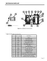
Table 12: optiTHERM Parts
ITEM
NO.
DESCRIPTION
PART NUMBER
ITEM
NO.
DESCRIPTION
PART NUMBER
1
Insulation, Tank Top
18229
18
Condensate Assembly Running Trap
19987
2
Baffle, 2”
16604
19
Cover, Exhaust, Right
19412
3
Second Pass Transition Cover
Contact Bock
20
Cover, Exhaust, Left
19413
4
Pipe Nipple, 2” x 5” x 8-1/4”, PS CE
15407
21
4-1/4” Cover Plate
17235
5
Cover, Ctrl Pnl, Right
17123
22
Cover, Ctrl Pnl, Left
17122
6
Tasseron Duplex Sensor, 0.25NPT, Brass
21594
23
Burner Bracket Refractory Disc
18008
7
T&P Valve, 1.5”, FVX-4
21800
24
Blower, Fasco, GPM 7.0-7H
19903
8
Anode, 200mm
15151
25
optiTHERM, Flame Rod, 4”
19853
9
Cap, Plastic, for 3” hole
17593
26
#8-32 x 1/4” Socket Head Cap Screw
25137
10
Hand Hole Gasket
15560
27
Gasket, optiTHERM Flame Rod
18209
11
Cover Plate, 8”
17190
28
4” Rubber Coupling
20537
12
Drain Valve, 3/4” NPT
15590
29
PVC Schedule 40 DWV Pipe 4” DIA x 4” L
18249
13
Anode, 500mm
15153
30
Reducer, 4”-6”, PVC
18248
14
Control Panel Assembly
SEE NOTE
31
Spark Igniter
19940
15
Spark Generator
19944
32
Gasket, Spark
17910
16
HB Fitting, 1/4” NPT x 1/4” Hose Barb
17277
33
Exhaust Assembly
25597
17
Tasseron Sensor, 1/4” NPT, SS
21596
Figure 40: optiTHERM Parts
Содержание OT600-A
Страница 35: ...SECTION IV INSTALLATION Page 35 Figure 26 Piping Diagram One Unit Figure 27 Piping Diagram Two Units ...
Страница 40: ...Page 40 SECTION IV INSTALLATION Figure 32 Component Wiring Diagram ...
Страница 41: ...Page 41 Figure 33 Schematic Wiring Diagram SECTION IV INSTALLATION ...
Страница 62: ...Page 62 ...