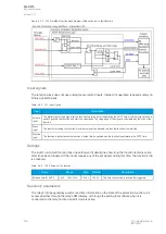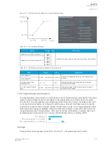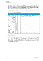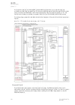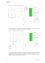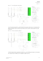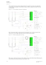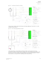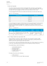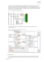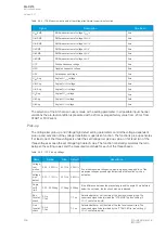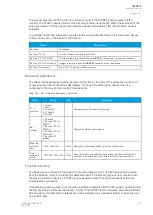
When the curve signal is out of range, it activates the "ASC1...4 input out of range" signal, which can
be used inside logic or with other relay functions. The signal can be assigned directly to an output relay
or to an LED in the I/O matrix. The "Out of range" signal is activated, when the measured signal falls
below the set input minimum limit, or when it exceeds the input maximum limit.
If for some reason the input signal is lost, the value is fixed to the last actual measured cycle value. The
value does not go down to the minimum if it has been something else at the time of the signal breaking.
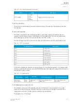
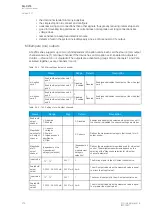
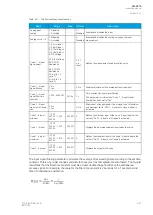
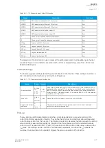
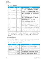
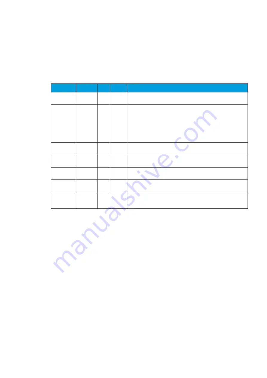
Table. 5.5.7 - 169. Output settings and indications.
Name
Range
Step Default
Description
Curve 1...4
update cycle
5...10
000ms
5ms
150ms
Defines the length of the input measurement update cycle. If the user wants
a fast operation, this setting should be fairly low.
Scaled value
handling
0: Floating
point
1: Integer
out (Floor)
2: Integer
(Ceiling)
3: Integer
(Nearest)
-
0:
Floating
point
Rounds the milliampere signal output as selected.
Input value 1
0...4000
0.000
01
0
The measured input value at Curve Point 1.
Scaled output
value 1
-10
7
...10
7
0.000
01
0
Scales the measured milliampere signal at Point 1.
Input value 2
0...4000
0.000
01
1
The measured input value at Curve Point 2.
Scaled output
value 1
-10
7
...10
7
0.000
01
0
Scales the measured milliampere signal at Point 2.
Add
curvepoint
3...20
0: Not
used
1: Used
-
0: Not
used
Allows the user to create their own curve with up to twenty (20) curve
points, instead of using a linear curve between two points.
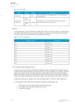
5.5.8 Logical outputs
Logical outputs are used for sending binary signals out from a logic that has been built in the logic
editor. Logical signals can be used for blocking functions, changing setting groups, controlling digital
outputs, activating LEDs, etc. The status of logical outputs can also be reported to a SCADA system.
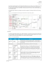
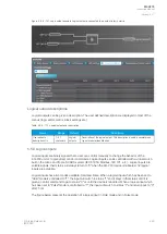
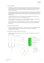
32 logical outputs are available. The figure below presents a logic output example where a signal from
the circuit breaker failure protection function controls the digital output relay number 5 ("OUT5") when
the circuit breaker's cart status is "In".
A
AQ
Q-C215
-C215
Instruction manual
Version: 2.07
222
© Arcteq Relays Ltd
IM00040
Содержание AQ-C215
Страница 1: ...AQ C215 Capacitor bank protection IED Instruction manual ...
Страница 2: ......
Страница 297: ...Figure 7 4 179 Example block scheme A AQ Q C215 C215 Instruction manual Version 2 07 Arcteq Relays Ltd IM00040 295 ...
Страница 318: ...Figure 8 14 200 Device installation A AQ Q C215 C215 Instruction manual Version 2 07 316 Arcteq Relays Ltd IM00040 ...
Страница 347: ...10 Ordering information A AQ Q C215 C215 Instruction manual Version 2 07 Arcteq Relays Ltd IM00040 345 ...


