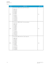
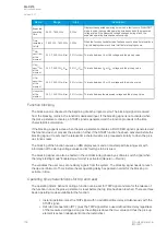
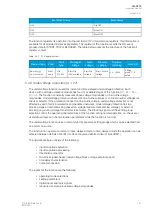


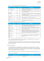


Table. 5.4.8 - 99. Measured magnitude selection settings.
Name
Description
Range
Step Default
Measured
magnitude
Selection of P-P or P-E voltages. Additionally, the U3 or U4 input can be
assigned as the voltage channel to be supervised.
0: P-P
voltages
1: P-E
voltages
2: U3 input
(2LL-U3SS)
3: U4 input
(SS)
-
0: P-P
voltages
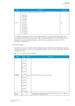
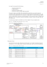
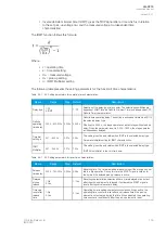
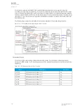
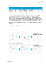
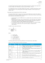
The selection of the AI channel in use is made with a setting parameter. In all possible input channel
variations the pre-fault condition is presented with a 20 ms averaged history value from -20 ms from
START or TRIP event.
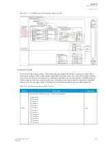
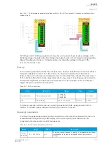
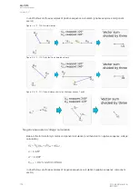
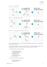
Figure. 5.4.8 - 101. Selectable measurement magnitudes with 3LN+U4 VT connection.
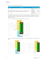
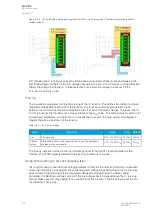
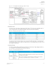
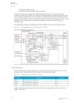
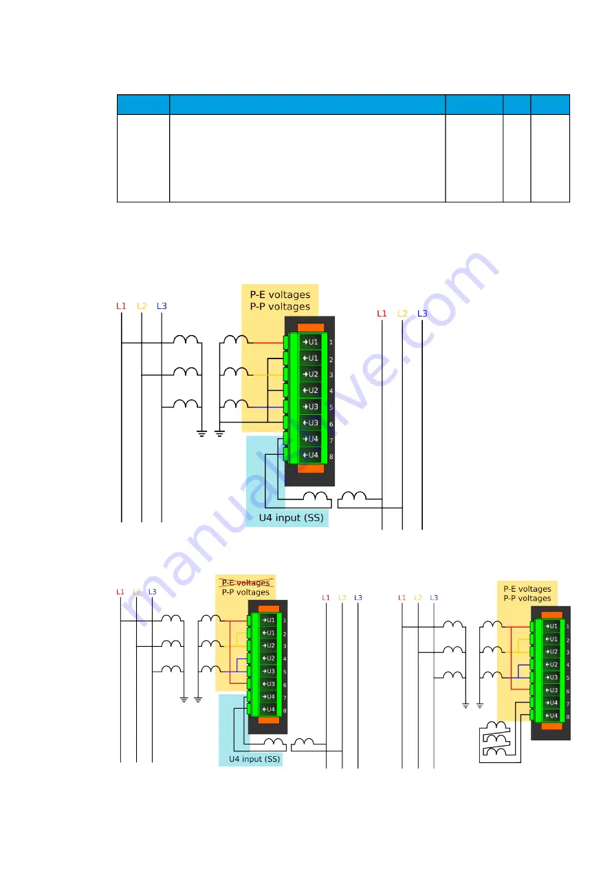
Figure. 5.4.8 - 102. Selectable measurement magnitudes with 3LL+U4 VT connection (P-E voltages not available without
residual voltage).
A
AQ
Q-C215
-C215
Instruction manual
Version: 2.07
© Arcteq Relays Ltd
IM00040
143
Содержание AQ-C215
Страница 1: ...AQ C215 Capacitor bank protection IED Instruction manual ...
Страница 2: ......
Страница 297: ...Figure 7 4 179 Example block scheme A AQ Q C215 C215 Instruction manual Version 2 07 Arcteq Relays Ltd IM00040 295 ...
Страница 318: ...Figure 8 14 200 Device installation A AQ Q C215 C215 Instruction manual Version 2 07 316 Arcteq Relays Ltd IM00040 ...
Страница 347: ...10 Ordering information A AQ Q C215 C215 Instruction manual Version 2 07 Arcteq Relays Ltd IM00040 345 ...


