
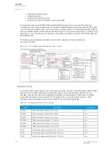
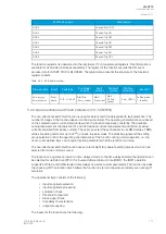
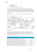

Function blocking
The block signal is checked in the beginning of each program cycle. The blocking signal is received
from the blocking matrix in the function's dedicated input. Additionally, the capacitor bank overload
function includes an internal inrush harmonic blocking option which is applied according to the
parameters set by the user. If the blocking signal is not activated when the pick-up element activates, a
START signal is generated and the function proceeds to the time characteristics calculation.
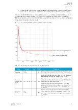
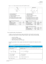
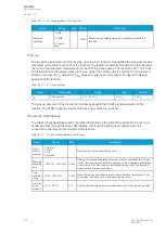
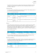
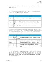
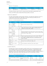
Table. 5.4.2.1 - 53. Internal inrush harmonic blocking settings.
Name
Range
Step
Default
Description
Inrush harmonic blocking (internal-
only trip)
0: No
1: Yes
-
0: No
Enables and disables the 2
nd
harmonic
blocking.
2
nd
harmonic blocking limit (Iharm/
Ifund)
0.10…50.00%I
fund
0.01%I
fund
0.01%I
fund
Defines the limit of the 2
nd
harmonic
blocking.
If the blocking signal is active when the pick-up element activates, a BLOCKED signal is generated and
the function does not process the situation further. If the START function has been activated before the
blocking signal, it resets and the release time characteristics are processed similarly to when the pick-
up signal is reset.
The blocking of the function causes an HMI display event and a-time stamped blocking event with
information of the startup current values and its fault type to be issued.
The blocking signal can also be tested in the commissioning phase by a software switch signal when
the relay's testing mode "Enable stage forcing" is activated (
General
→
Device).
The variables the user can set are binary signals from the system. The blocking signal needs to reach
the deviceminimum of 5 ms before the set operating delay has passed in order for the blocking to
activate in time.
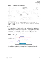
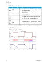
Operating time characteristics for trip and reset
This function supports definite time delay (DT) and inverse definite minimum time delay (IDMT) with
user-programmable characteristics.
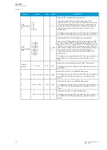
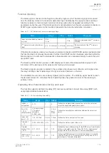
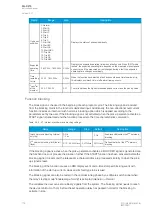
Table. 5.4.2.1 - 54. Icol> operating time setting.
Name
Range
Step
Default
Description
Im/Iset / t
curvepoints
2...10
1
2
Defines the programmable measured current or the set current
versus the expected operating time points.
Point 1(9)
– 2(10)
characteristics
0: Two point steps
1: Two point
interpolate
2: IDMT curve
-
0: Two
point
steps
Defines the operating time calculation between the set current
points.
Imeas / Iset
point 1...10
1.00...40.00xIn
0.01xIn 1.00xIn
Defines the first current point of the curve.
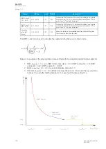
Time point
1...10
0.005...3600.000s 0.01s
1.00s
Defines the first time point of the curve.
Time dial
setting k 1(9)
– 2(10)
0.01...25.00
0.01
1.00
Defines the time multiplier setting for the IDMT curve. Note that this
setting is only visible when the "Point 1(9)–2(10) characteristics"
setting is set to "Two point steps" or "Two point interpolate".
IDMT Const A
1(9) – 2(10)
0.01...25.00
0.01
1.00
Defines the IDMT constant A. Note that this setting is only visible
when the "Point 1(9)–2(10) characteristics" setting is set to "Two
point steps" or "Two point interpolate".
A
AQ
Q-C215
-C215
Instruction manual
Version: 2.07
© Arcteq Relays Ltd
IM00040
105
Содержание AQ-C215
Страница 1: ...AQ C215 Capacitor bank protection IED Instruction manual ...
Страница 2: ......
Страница 297: ...Figure 7 4 179 Example block scheme A AQ Q C215 C215 Instruction manual Version 2 07 Arcteq Relays Ltd IM00040 295 ...
Страница 318: ...Figure 8 14 200 Device installation A AQ Q C215 C215 Instruction manual Version 2 07 316 Arcteq Relays Ltd IM00040 ...
Страница 347: ...10 Ordering information A AQ Q C215 C215 Instruction manual Version 2 07 Arcteq Relays Ltd IM00040 345 ...


