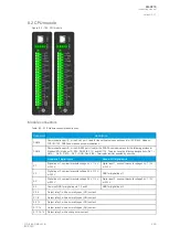
Scanning cycle
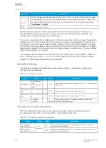
All digital inputs are scanned in a 5 ms cycle, meaning that the state of an input is updated every 0…5
milliseconds. When an input is used internally in the device (either in setting group change or logic), it
takes additional 0…5 milliseconds to operate. Theoretically, therefore, it takes 0…10 milliseconds to
change the group when a digital input is used for group control or a similar function. In practice,
however, the delay is between 2…8 milliseconds about 95 % of the time. When a digital input is
connected directly to a digital output (T1…Tx), it takes an additional 5 ms round. Therefore, when a
digital input controls a digital output internally, it takes 0…15 milliseconds in theory and 2…13
milliseconds in practice.
Please note that the mechanical delay of the relay is no
nott included in these approximations.
8.3 Current measurement module
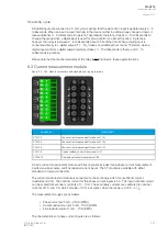
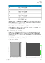
Figure. 8.3 - 183. Module connections with standard and ring lug terminals.
Connector
Description
CTM 1-2
Phase current measurement for phase L1 (A).
CTM 3-4
Phase current measurement for phase L2 (B).
CTM 5-6
Phase current measurement for phase L3 (C).
CTM 7-8
Coarse residual current measurement I01.
CTM 9-10
Fine residual current measurement I02.
A basic current measurement module with five channels includes three-phase current measurement
inputs as well as coarse and fine residual current inputs. The CT module is available with either
standard or ring lug connectors.
The current measurement module is connected to the secondary side of conventional current
transformers (CTs). The nominal current for the phase current inputs is 5 A. The input nominal current
can be scaled for secondary currents of 1…10 A. The secondary currents are calibrated to nominal
currents of 1 A and 5 A, which provide ±0.5 % inaccuracy when the range is 0.005…4 ×
I
n
.
The measurement ranges are as follows:
• Phase currents 25 mA…250 A (RMS)
• Coarse residual current 5 mA…150 A (RMS)
• Fine residual current 1 mA…75 A (RMS)
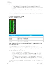
The characteristics of phase current inputs are as follows:
A
AQ
Q-C215
-C215
Instruction manual
Version: 2.07
© Arcteq Relays Ltd
IM00040
301
Содержание AQ-C215
Страница 1: ...AQ C215 Capacitor bank protection IED Instruction manual ...
Страница 2: ......
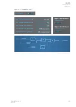
Страница 297: ...Figure 7 4 179 Example block scheme A AQ Q C215 C215 Instruction manual Version 2 07 Arcteq Relays Ltd IM00040 295 ...
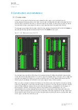
Страница 318: ...Figure 8 14 200 Device installation A AQ Q C215 C215 Instruction manual Version 2 07 316 Arcteq Relays Ltd IM00040 ...
Страница 347: ...10 Ordering information A AQ Q C215 C215 Instruction manual Version 2 07 Arcteq Relays Ltd IM00040 345 ...

