Installation
8
NXD-500i 5" Modero Wall/Flush Mount Touch Panel with Intercom
6.
Connect both connectors to their corresponding locations along the left side of the NXD-500i touch panel.
7.
Test the incoming wiring by attaching the panel connections to their terminal locations and applying power via the
PoE Injector. Verify that the panel is receiving power and functioning properly to prevent repetition of the
installation.Test the incoming wiring by connecting the panel connections to their terminal locations and applying
power via the PoE Injector. Verify that the panel is receiving power and functioning properly to prevent repetition of
the installation.
8.
Install the NXD-500i into the back box.
9.
The microphone cable is taped to the back box. Connect the microphone cable to its connector, making sure that the
cable does not interfere with reattachment of the Faceplate.
10.
Install the two Plastite screws attaching the NXD-500i to the back box (FIG. 5).
11.
Place the Faceplate/Trim Ring assembly (
A
in
FIG. 5) back onto the main NXD-500i unit (
B
in
FIG. 5).
Make sure
to align the Microphone, Light, and PIR Motion sensor locations to their respective openings on the front faceplate/
bezel.
12.
Reconnect the terminal Ethernet and USB to their respective locations on the Ethernet port and NetLinx Master.
Installing the NXD-500i Into Drywall
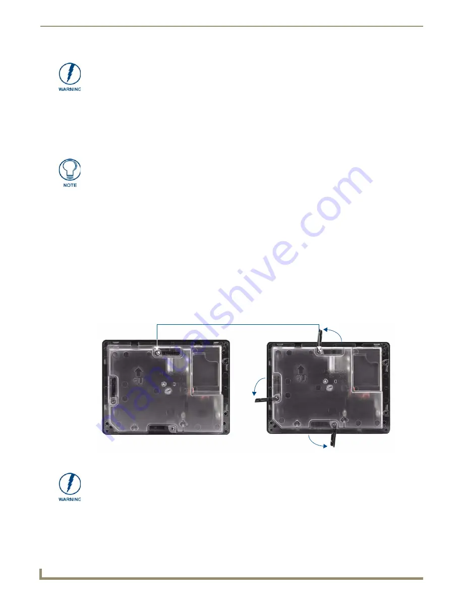
The NXD-500i comes with a clear plastic backbox (FIG. 6) designed to attach the panel to standard drywall. This
backbox has a locking tab on three of the four faces (missing only on the face containing the space for the connections)
to help lock the backbox to the wall.
These locking tabs are only extended AFTER the backbox is inserted into the wall.
Refer to the diagram for detailed installation dimensions as shown in FIG. 7.
Cutting out the surface slightly smaller than what is outlined in the installation drawings, in order to make any
necessary cutout adjustments, is highly recommended.
The maximum recommended torque to screw in the locking tabs on the back box is 5
IN-LB [56 N-CM]. Applying excessive torque while tightening the locking tab screws,
such as with powered screwdrivers, can strip out the tabs or damage the back box.
Do not disconnect the connectors from the touch panel. The unit must be installed
with the attached connectors before being inserted into the Rough-In Box.
FIG. 6
NXD-500i backbox with closed and open locking tabs
Locking tabs - Closed
Locking tabs - Open
Locking tab screws
When installing the backbox, make absolutely sure that the assembly is in the correct
position and in the correct place.
Once the locking tabs are extended and locked into place, removing the backbox will
be very difficult without having access to the back of the wall itself or damaging the
wall.
Содержание Modero NXD-500i
Страница 4: ......
Страница 12: ...viii NXD 500i 5 Modero Wall Flush Mount Touch Panel with Intercom Table of Contents...
Страница 30: ...NXD 500i Touch Panel Accessories 18 NXD 500i 5 Modero Wall Flush Mount Touch Panel with Intercom...
Страница 32: ...Panel Calibration 20 NXD 500i 5 Modero Wall Flush Mount Touch Panel with Intercom...
Страница 130: ...Programming 118 NXD 500i 5 Modero Wall Flush Mount Touch Panel with Intercom...
Страница 134: ...Troubleshooting 122 NXD 500i 5 Modero Wall Flush Mount Touch Panel with Intercom...
Страница 140: ...Appendix A Text Formatting Codes 128 NXD 500i 5 Modero Wall Flush Mount Touch Panel with Intercom...
Страница 143: ...Appendix B Complex Script Support 131 NXD 500i 5 Modero Wall Flush Mount Touch Panel with Intercom...


