


18
R
EV
9
A
MERICAN
M
AGNETICS
, I
NC
.
I
NSTALLATION
: S
YSTEM
I
NTERCONNECTS
(S
INGLE
-A
XIS
S
YSTEMS
)
U
NIPOLAR
P
OWER
S
UPPLY
S
YSTEM
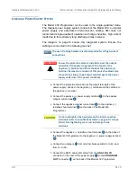
The Model 430 Programmer can be used in the single-quadrant mode.
The magnet power supply system consists of the Model 430, a unipolar
power supply and associated interconnection cabling. AMI does not
recommend single-quadrant operation with large inductive, high-current
loads due to the extremely long discharge times involved.
The diagram on page 19 shows this integrated system. Ensure the
cabling is connected in the following manner:
NOTE
The use of locking hardware is recommended for all high-current
connections.
WARNING
Ensure the protective diode is installed across the output
terminals of the power supply with the anode at the
negative (–) terminal and the cathode at the positive (+)
terminal. Removal or omission of this protective diode may
cause serious injury to personnel and damage to the power
supply under loss of AC power conditions.
a. Connect the protective diode across the output terminals of the
power supply: anode to the negative (–) terminal and the cathode to
the positive (+) terminal.
b. Connect the positive (+) power supply terminal
ì
to the positive
magnet current lead
î
.
c. Connect the negative magnet current lead
ï
to the positive (+)
resistive shunt terminal
ñ
on the back of the Model 430
Programmer.
CAUTION
Do not overtighten the hardware on the interconnection
terminals (refer to specifications table on page 8 for torque
limits). Overtightening can result in damage to the
terminals.
d. Connect the negative (
−
) resistive shunt terminal
ó
on the back of
the Model 430 Programmer to the negative (–) power supply terminal
r
.
e. Connect two jumpers
~â
from terminal block position S- to M- and
from S+ to M+.
f. Connect the DB15 analog I/O cable from the
ANALOG I/O
connector on the rear of the power supply
s
to the
PROGRAM
OUT
connector
~ã
on the back of the Model 430 Programmer.
Содержание 430
Страница 2: ......
Страница 16: ...XVI REV 9 AMERICAN MAGNETICS INC FOREWORD SAFETY SUMMARY ...
Страница 28: ...12 REV 9 AMERICAN MAGNETICS INC INTRODUCTION OPERATING CHARACTERISTICS ...
Страница 64: ...48 REV 9 AMERICAN MAGNETICS INC INSTALLATION POWER UP AND TEST PROCEDURE ...
Страница 208: ...192 REV 9 AMERICAN MAGNETICS INC SERVICE RETURN AUTHORIZATION ...
Страница 248: ...232 REV 9 AMERICAN MAGNETICS INC APPENDIX SHORT SAMPLE MODE ...


