66
R
EV
9
A
MERICAN
M
AGNETICS
, I
NC
.
O
PERATION
: SHIFT+
KEY
C
OMMANDS
/ M
ENUS
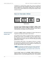
Any unused segment(s) above the Current Limit will remain in
memory (retaining their original parameters) until one or more
become active again when the Current Limit is raised into or
above the respective ranges. When displayed, the higher-range
unused
segments will show a range of “±Limit to ±Limit” until re-
activated
20
.
V
OLTAGE
L
IMIT
(S
HIFT
+
2)
Use of the
VOLTAGE LIMIT (
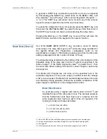
SHIFT+2) key provides a menu for setting
the limit for output voltage for the power supply the Model 430
Programmer controls. This value should be set to a high enough value
so that under normal conditions, the Voltage Limit is never reached. The
value can be set by using either the numeric keypad entry as described
page 54 or the fine adjust knob (on page 55).
Note that the voltage drop in the leads must be accounted for when
setting the Voltage Limit, as well as the voltage drop of an energy
absorber if in use (see page 110 for details of how to determine the
appropriate Voltage Limit).
The Voltage Limit may be set less than or equal to the maximum output
voltage of the power supply.
21
The Voltage Limit functions as a bipolar
limit.
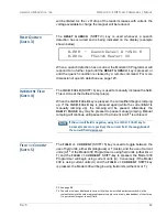
If Voltage Limit becomes active while ramping, it will be indicated by a
reverse illumination character “V” for the status indicator.
Once the Voltage Limit function becomes active, the current, and
therefore field, will no longer be ramping linearly with time as the voltage
available to charge the magnet will be reduced as the total loop voltage
20. Also if the number of segments is increased, the new segments are added to the upper end
of the ramp range, and default to the ramp rate of the previous segment with the range of
±Limit to ±Limit until set up.
+50.00 A - Seg.3 Range (A)
+0.50 Vs
±Limit to ±Limit
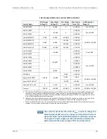
21. Refer to the table on page 75.
+50.00 A - Voltage Limit (V)
+0.50 Vs
±2.000
+40.92 A
Mode: Ramping
+2.50 Vs
V
PSwitch Heater: ON
Содержание 430
Страница 2: ......
Страница 16: ...XVI REV 9 AMERICAN MAGNETICS INC FOREWORD SAFETY SUMMARY ...
Страница 28: ...12 REV 9 AMERICAN MAGNETICS INC INTRODUCTION OPERATING CHARACTERISTICS ...
Страница 64: ...48 REV 9 AMERICAN MAGNETICS INC INSTALLATION POWER UP AND TEST PROCEDURE ...
Страница 208: ...192 REV 9 AMERICAN MAGNETICS INC SERVICE RETURN AUTHORIZATION ...
Страница 248: ...232 REV 9 AMERICAN MAGNETICS INC APPENDIX SHORT SAMPLE MODE ...


