


86
R
EV
9
A
MERICAN
M
AGNETICS
, I
NC
.
O
PERATION
: S
ETUP
S
UBMENU
D
ESCRIPTIONS
: S
WITCH
S
UBMENU
install an external jumper cable from one of the Magnet Station
connectors to the Auxiliary Input 1 to use the magnet voltage
based switch transition feature. See page 202 for more details.
NOTE
The magnet voltage method of sensing persistent switch
transitions
requires
the magnet voltage input to the rear panel
Magnet Station connector as described on page 193. Please note
that some magnet system manufacturers do not provide magnet
voltage taps.
PS
WITCH
H
EATED
T
IME
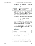
The persistent switch heated time is only displayed for, and
applies only to, the timer-based switch transition method and is
the amount of time required for the persistent switch to heat
completely and become fully normal (resistive). The time may be
set to any value between 5 and 120 seconds
37
. The value can be
set by using either the numeric keypad as described on page 54
or the fine adjust knob (on page 55). The default is 20 seconds
unless preset by AMI to match a specific superconducting
magnet.
During the persistent switch heating period, the Model 430
Programmer ramping functions are disabled. The time delay is
necessary to ensure that the Model 430 will not switch to the
higher control gain required for proper magnet operation before
the magnet is actually available in the circuit (not being shunted
by the persistent switch). If magnet operation is not stable after
expiration of the heating period, increase the heated time to allow
more time for the switch to heat. The default value of 20 seconds
is adequate for the majority of wet and dry persistent switches.
PS
WITCH
C
OOLED
T
IME
The PSwitch Cooled Time is only displayed for, and applies only
to, the timer-based switch transition method and is the amount of
37. During the heating cycle, a “countdown” will be displayed indicating the number of seconds
remaining in the cycle.
+50.00 A — PSwitch Heated Time (sec)
+0.50 Vs
20
+50.00 A — PSwitch Cooled Time (sec)
+0.50 Vs
20
Содержание 430
Страница 2: ......
Страница 16: ...XVI REV 9 AMERICAN MAGNETICS INC FOREWORD SAFETY SUMMARY ...
Страница 28: ...12 REV 9 AMERICAN MAGNETICS INC INTRODUCTION OPERATING CHARACTERISTICS ...
Страница 64: ...48 REV 9 AMERICAN MAGNETICS INC INSTALLATION POWER UP AND TEST PROCEDURE ...
Страница 208: ...192 REV 9 AMERICAN MAGNETICS INC SERVICE RETURN AUTHORIZATION ...
Страница 248: ...232 REV 9 AMERICAN MAGNETICS INC APPENDIX SHORT SAMPLE MODE ...


