46
R
EV
9
A
MERICAN
M
AGNETICS
, I
NC
.
I
NSTALLATION
: P
OWER
-U
P
AND
T
EST
P
ROCEDURE
NOTE
If energy absorbers are in use, ensure all the power adapters are
properly connected to the energy absorbers and their respective
AC power receptacles.
4. When prompted by the Model 430 Programmer, energize the power sup-
ply(s), allow an appropriate amount of time for the supply(s) to start (some
produce an audible “click” during power-up), and then press
ENTER
on the
Model 430 Programmer. If there is more than one power supply, observe the
proper master/slave power-up procedure.
5. Configure the Model 430 Programmer for
Test
Stability Mode. Refer to
NOTE
The Model 430 Programmer Stability Mode must be set to
Test
for
the power supply system to be stable on a short circuit test load.
6. Verify the various setup menu values for the system. If the power supply sys-
tem was purchased with an AMI magnet, AMI has preset the setup menu
values for proper operation. See page 72 for more discussion of the setup
menu values and their entry into the Model 430 Programmer.
7. Set the Target Setpoint to 10 A. Refer to page 54 and page 61.
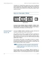
8. Initiate ramping to the target current by pressing the
RAMP / PAUSE
key
(status indicator changes from
P
to
).
9. The system should ramp to 10 A in approximately 2 seconds.
6
Verify this is
the case.
NOTE
IfWith an energy absorber unit is connected, the Model 430
Programmer may take significantly longer to ramp the current to
10 A. The Model 430 must first develop a supply output voltage to
overcome the forward voltage drop of a connected energy
absorber. During actual magnet operation, the presence of an
energy absorber will not significantly delay the ramping operation
since the Model 430 control gain is increased by orders of
magnitude when an inductive load is connected.
10.When the target current is achieved, the
FIELD AT TARGET
LED will be
illuminated. The display should show “
+10.00 A -
”
indicating that the
Model 430 Programmer is in the holding mode at the target current value
(+10.00 A).
11.If the connected power supply has a display, verify that the power supply out-
put current display indicatess that a total of approximately 10 A is being sup-
plied to the load (which is only the cabling in this case).
6. When controlling a magnet, the ramp is very accurate because the system gain is relatively
high. When controlling current through a short-circuit, the loop gain is relatively low and it is
difficult to track high ramp rates.
Содержание 430
Страница 2: ......
Страница 16: ...XVI REV 9 AMERICAN MAGNETICS INC FOREWORD SAFETY SUMMARY ...
Страница 28: ...12 REV 9 AMERICAN MAGNETICS INC INTRODUCTION OPERATING CHARACTERISTICS ...
Страница 64: ...48 REV 9 AMERICAN MAGNETICS INC INSTALLATION POWER UP AND TEST PROCEDURE ...
Страница 208: ...192 REV 9 AMERICAN MAGNETICS INC SERVICE RETURN AUTHORIZATION ...
Страница 248: ...232 REV 9 AMERICAN MAGNETICS INC APPENDIX SHORT SAMPLE MODE ...


