background image

Charge Controller Settings


104


900-0117-01-00 Rev A 

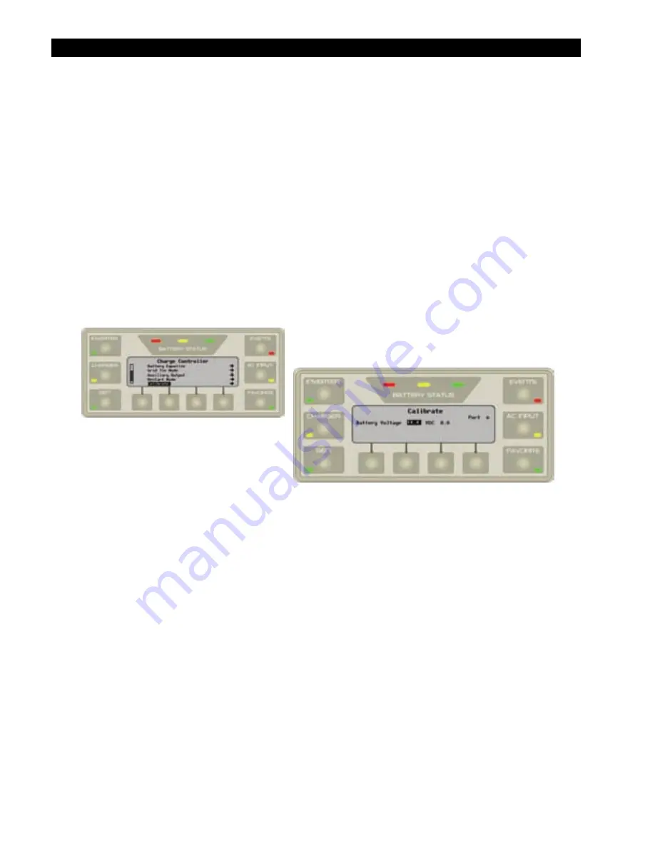
Calibrate  


The Calibrate menu allows adjustment of the charge controller’s battery voltmeter.  If a particular 
controller’s readings do not match those of another device, or a handheld meter, the calibration feature 
may improve consistency.   

To 

access 

the 

Calibrate

 menu: 

1.


Access the 

Charge Controller

 menu as shown in Figure 90 on page 94. 

2.


Use the control wheel to highlight the 

Calibrate


menu.  

Press the button in the center of the control wheel to accept the selection.   

3.


Use the control wheel to increase or decrease the set points to the correct voltage.  Press the button in 
the center of the control wheel to accept the selection.  This should automatically move the 
highlighting to the next set point. 

4.


After setting the parameters for each set point, press the 

TOP

 navigation key to return to the 

Main Menu

 screen. 


Figure 104  Calibrate 

Set Points: 


Battery Voltage: 

 Calibrates the DC voltage measurement made at the charge controller’s battery 

terminals.    


Figure 104 shows the current reading being taken by the charge controller in Vdc.  However, the field 
to the right is the calibration setting. 

Note

:  Calibration does not change the actual voltage of the charge controller, only the reading of that 

voltage. 

Also, measurements in places other than the charge controller’s terminals may differ regardless of 
calibration.  For example, it is possible to get a different reading at the charge controller’s DC terminals 
than on the batteries.  Connection problems, corrosion, and the effects of induction and resistance may all 
result in voltage differences.  If this occurs, note that this is an issue with the system, not the inverter.  
Calibration cannot correct for it. 


Содержание OutBack Power MATE3

Страница 1: ...MATE3 System Display and Controller Owner s Manual ...

Страница 2: ... IN ITS MANUALS OR OTHER DOCUMENTATION b ASSUMES NO RESPONSIBILITY OR LIABILITY FOR LOSS OR DAMAGE WHETHER DIRECT INDIRECT CONSEQUENTIAL OR INCIDENTAL WHICH MIGHT ARISE OUT OF THE USE OF SUCH INFORMATION THE USE OF ANY SUCH INFORMATION WILL BE ENTIRELY AT THE USER S RISK Warranty Summary OutBack Power Technologies Inc warrants that the products it manufactures will be free from defects in material...

Страница 3: ...ation operation and or maintenance of the equipment Failure to follow the recommendations in such a notation could result in voiding the equipment warranty Audience This manual is intended for use by anyone required to install and operate this equipment Be sure to review this manual carefully to identify any potential safety risks before proceeding Familiarize yourself with all the features and fu...

Страница 4: ...ical products LBCI Low Battery Cut In the recovery point from Low Battery Cut Out LBCO Low Battery Cut Out set point at which the inverter shuts down due to low batteries LED Light Emitting Diode refers to indicators used by the inverter and the MATE3 NEC National Electric Code Off grid Utility grid power is not available for use On grid Utility grid power is available for use does not imply grid ...

Страница 5: ...to identify all possible sources of energy Ensure ALL sources of power are disconnected before performing any installation or maintenance on this equipment Confirm that the terminals are de energized using a validated voltmeter rated for a minimum 1000 Vac and 1000 Vdc to verify the de energized condition WARNING Fire Hazard Do not operate the unit with damaged or substandard cabling CAUTION Equip...

Страница 6: ... to radio or television reception which can be determined by turning the equipment off and on the user is encouraged to try to correct the interference by one or more of the following measures Reorient or relocate the receiving antenna Increase the separation between the equipment and the receiver Consult the dealer or an experienced radio TV technician for help Regulatory References These documen...

Страница 7: ...e 1 480 337 3025 direct Environmental Protection Agency USA Web site www epa gov recyclecity Phone 1 415 947 8000 Monday Friday 8 00 AM to 12 00 PM and 1 00 PM to 4 00 PM PST Email r9 recyclecity epa gov Keep America Beautiful USA Web site www kab org Address 1010 Washington Boulevard Stamford CT 06901 Phone 1 203 659 3000 Main number Fax 1 203 659 3001 Email info kab org OurEarth org USA There is...

Страница 8: ...nagement Conservation and Protection Environment Canada Ottawa Ontaro K1A 0H3 Phone 1 819 997 2800 Web site http www portaec net library recycling recycling_in_canada html EuroRecycle net Europe The following website provides general information about recycling in Europe It also provides a list of companies and organizations that provide recycling information or assistance Web site http euro recyc...

Страница 9: ... of Waste Management Canada 6 EuroRecycle net Europe 6 Introduction 13 Purpose 13 Functions 13 Features 13 Installation 15 Location Considerations 15 Mounting Considerations 15 Materials Included 15 Dimensions 16 To Install the MATE3 16 Set Points 19 Types of Settings 19 Communication Protocol 19 Software Required 19 Hardware Required 19 Operation 21 Display and LED Indicators 21 LED Status Indica...

Страница 10: ... Settings Menus 62 System Settings 63 System Information 64 Date Time 65 LCD Display 66 Sound 67 Ethernet Addresses 68 Ethernet Ports 69 Data Stream 70 Installer Settings 71 Inverter Settings 75 Search Menu 76 AC Input Current Limit 77 Grid AC Input Voltage Limits 79 Gen AC Input Voltage Limits 80 AC Output 81 Low Battery 82 Battery Charger 83 Battery Equalize 84 Auxiliary Output 85 Inverter Stack...

Страница 11: ... FLEXnet DC Advanced Control 132 Reset to Factory Defaults Screens 133 Configuration Wizard 134 Data Logs 134 Event Logs 134 Software Update 135 Troubleshooting 137 Basic Troubleshooting of the MATE3 137 Event Messages 138 Specifications 141 Mechanical Specifications 141 Menu Map 143 Product Registration 149 Warranty 151 How to Arrange for Warranty Service 152 Contacting OutBack 152 Troubleshootin...

Страница 12: ...f Grid Home Screen 29 Figure 12 Battery Soft Key 29 Figure 13 Battery Soft Key Screens without a FLEXnet DC Monitor 30 Figure 14 Battery Soft Key Screens with a FLEXnet DC Monitor 31 Figure 15 Next Soft Key with FLEXnet DC 32 Figure 16 Stats Soft Key with FLEXnet DC 32 Figure 17 Shunts Soft Key and Shunt Data with FLEXnet DC 33 Figure 18 DataLog Soft Key Screen with FLEXnet DC 34 Figure 19 Graph S...

Страница 13: ... 62 Figure 59 Accessing the Systems Settings Menu 63 Figure 60 System Information Menu Item 64 Figure 61 Date Time Menu Item 65 Figure 62 LCD Display 66 Figure 63 Sound 67 Figure 64 Ethernet Addresses 68 Figure 65 Ethernet Ports 69 Figure 66 Data Stream Screen 70 Figure 67 Installer Settings Screen 71 Figure 68 Set User Access Level 72 Figure 69 Change Installer Password 73 Figure 70 Challenge Ins...

Страница 14: ...sing the MATE Menu Items 113 Figure 114 Advanced Generator Start AGS Menu 114 Figure 115 AGS Setup Screen 115 Figure 116 AGS Functional Test 117 Figure 117 MATE AGS Voltage Start Screen 118 Figure 118 MATE AGS Load Start Screen 119 Figure 119 MATE AGS State of Charge Start Screen 120 Figure 120 MATE AGS Must Run Schedule Screen 121 Figure 121 MATE AGS Quiet Time Schedule Screen 122 Figure 122 MATE...

Страница 15: ...erator Start AGS Mode based on voltage load time of day and the state of charge of the batteries Control auxiliary AC or DC loads such as cooling fans and relays Links to as many as ten OutBack Inverter Chargers and OutBack charge controllers OutBack HUB Communications Manager is required Issue a global Bulk or EQ recharging command which includes the charge controller s charging function OutBack ...

Страница 16: ... FAVORITE Hot Key Favorite Status LED Green Battery Status LEDs x3 LCD Screen Soft Keys x4 PORT Navigation Key UP Navigation Key LOCK Key TOP Navigation Key Control Wheel ENTER Button CHARGER Hot Key Charger Status LED Green SD Memory Card Slot SD Memory Card Ethernet Port Computer Back View Side View Port to HUB or OutBack Device GEN erator Hot Key GEN Status LED Green ...

Страница 17: ...degradation can result if cable is run in conduit with AC wiring or in other electronically noisy environments these can affect the maximum length the cable can run without incurring transmission errors Mounting Considerations The MATE3 includes 1 OBCAT 6 Cat5 cable with the correct RJ45 connectors already installed Longer up to 1000 or shorter cables can be purchased pre made at home improvement ...

Страница 18: ...cable to the source but not to the MATE3 4 Power up each OutBack device connected directly or indirectly through the HUB to the MATE3 5 Then connect the CAT5 cable to the port on the MATE3 6 Secure the MATE3 to the mounting surface or mounting bracket if present If a mounting bracket is used install the mounting bracket using the instructions supplied with the bracket If a mounting bracket is not ...

Страница 19: ...Figure 3 MATE3 Connections no HUB NOTE The MATE3 can also be connected directly to a charge controller It cannot be connected directly to a FLEXnet DC monitor without a HUB and other OutBack devices such as an inverter or charge controller ...

Страница 20: ...Installation 18 900 0117 01 00 Rev A Figure 4 MATE3 Connections with HUB This feature is not implemented at this time ...

Страница 21: ...ngs and values that occur while the system is running From time to time these settings and values might be adjusted as components are added or upgraded electrical loads increase or patterns of usage change Types of Settings The OutBack MATE3 accommodates a wide range of time based and voltage level functions and conditions for maximum control of the power system The following types of settings may...

Страница 22: ...Installation 20 900 0117 01 00 Rev A THIS PAGE INTENTIONALLY LEFT BLANK ...

Страница 23: ...anged even after the MATE3 is removed If a system does not have a MATE3 an installer can bring a MATE3 to the site temporarily install it change the settings and then remove it IMPORTANT Some functions are not based in the inverter but are part of the MATE3 s software They will not function if the MATE3 is removed These functions are listed beginning on page 112 Display and LED Indicators Figure 5...

Страница 24: ...ltage units are due to the resolution of the inverter s DC meter 2 These voltage settings are not the same as the inverter s Low Battery Cut Out LBCO voltage The Battery LED settings cannot be changed Inverter LED green This LED is located on the INVERTER hot key See page 47 It provides a visual reference for the status of the inverter operation ON solid inverter is converting DC to AC in order to...

Страница 25: ...urred OFF not illuminated No event has occurred This LED will remain on until the event has been acknowledged in the Event Status Detail menu See page 53 It may be necessary to troubleshoot and deal with the cause of the event using the Inverter soft key See page 37 40 Specific error or warning messages are defined in the inverter Operator s Manual AC Input LED yellow This LED is located on the AC...

Страница 26: ... Favorite OFF not illuminated No particular status The Favorite LED only illuminates in response to the hot key being pressed Power Up Screens The MATE3 powers up as soon as it is plugged into a powered OutBack product It will immediately cycle through the startup screens It will proceed to locate and identify the attached components and the ports they occupy on the HUB It will then stop on the Ho...

Страница 27: ...lemented at this time Do not select Meter Bars Much of the Home screen data is shown by kilowatt meters in the form of black bars These meter bars expand to right or left with an increase in wattage The meter bars next to the various icons are based on System Information listed on page 64 The scale of a bar will vary with the size set for each element The meter bar is scaled according to the Array...

Страница 28: ...in the top right corner of the screen marks a percentage meter that shows the SOC of the batteries as measured by the battery monitor If no battery monitor is present this figure will be replaced by another battery voltage meter The PV symbol in the lower left of the screen marks a kilowatt meter that measures the amount of PV power generated The PV symbol next to the bar shows a graphic display o...

Страница 29: ...bar expands from left to right The house symbol next to the meter bar measures power delivered to the inverter s output This meter bar expands from left to right The PV symbol in the lower left of the screen marks a kilowatt meter that measures the amount of PV power generated The PV symbol next to the bar shows a graphic display of the PV power generated This meter expands from left to right If n...

Страница 30: ...hot key which is a MATE3 feature that is always available see page 47 The two keys display nominally similar information but the Inverter soft key has more information Additionally the INVERTER hot key can control the inverting function and the Inverter soft key cannot The far left key or Charge Controller soft key displays information on any FLEXmax charge controllers present on the HUB If no cha...

Страница 31: ...id Home Screen Battery Soft Key Figure 12 Battery Soft Key If no FLEXnet DC battery monitor is present on the system the battery soft key brings up the following screens Home Screen Battery Soft Key Press this soft key to view Battery status information Generator Source ...

Страница 32: ...y voltage for that day and the time it was recorded Max displays the highest recorded battery voltage for that day and the time it was recorded Soft Keys Graph brings up a single graph showing changes in battery voltage over time This is the same graph shown on pages 34 41 and 44 Back returns to the previous screen This axis shows battery voltage This axis shows date and time in 6 hour increments ...

Страница 33: ...right this line displays the total amp hours and kilowatt hours removed from the batteries that day Bat displays the net total current and kilowatts being sent to or taken from the batteries To the right this line displays the net total amp hours and kilowatt hours accumulated or taken from the batteries that day The last line shows both the highest and lowest recorded battery SOC for that day and...

Страница 34: ...iency Total Days at 100 displays the number of days since the batteries reached 100 SOC If the batteries are not at 100 this will read 0 Lifetime kAH Removed accumulates the total amp hours that were ever drained from the batteries Soft Keys Back returns to the previous screen Reset Days resets the Total Days at 100 Reset kAH resets the Lifetime kAH removed Screen Items Bat displays battery voltag...

Страница 35: ...ed to Battery and Removed from Battery show the total accumulated amp hours that have been delivered to the battery bank as charging or removed from the battery bank as loads Max Charge Rate and Max Discharge Rate show the highest level of current that was registered either entering charging or leaving discharging the batteries The Reset Max soft key can reset both numbers at once Soft Keys The Ne...

Страница 36: ...single day and will display the selected date Back returns to the previous screen Screen Items Today The item in the upper left corner shows the date of the selected Datalog screen The current Datalog screen reads Today Minimum SOC shows the lowest battery state of charge SOC for that day Input shows the number of amp hours and kilowatt hours brought into the batteries that day Output shows the nu...

Страница 37: ... plot various type of data over time The first screen shows changes in battery voltage over time This is the same graph shown on pages 30 42 and 45 Figure 19 Graph Soft Key with FLEXnet DC Figure 20 Battery Voltage Graph with FLEXnet DC This axis shows battery voltage This axis shows date and time in 6 hour increments ...

Страница 38: ...Shunt A Figure 22 Shunt A Graph with FLEXnet DC Continuing to press the Next soft key will proceed to Shunts B and C if they have been enabled A shunt that is not enabled will not display a graph After the shunts have appeared the Next soft key will return to the Battery graph This axis shows the wattage readings calculatedfrom shunt A This axis shows date and time in 6 hour increments This axis s...

Страница 39: ... the Charge and Load items Battery displays the uncompensated battery voltage AC Out displays the AC voltage measured at the inverter s output If an AC source is present this reading is usually the same as AC In AC In displays the AC voltage measured at the inverter s input from an AC source The lower right corner shows the current status of the inverter s Auxiliary AUX output See page 83 Soft Key...

Страница 40: ... the inverter s charger During the float stage this is the target voltage used by the charger Equalize displays the Equalization voltage setting which was programmed into the inverter s charger During the equalization charging cycle this is the target voltage used by the charger Temp Comp displays the corrected battery voltage after temperature readings are taken into account from the Remote Tempe...

Страница 41: ...r acceptable voltage limit and prevents connection Input Amps Max AC loads are drawing more current from the AC source than allowed by the input setting Temp Sensor Bad An internal inverter temperature sensor may be malfunctioning This is indicated by an unusual Transformer Output FETs or Capacitors reading Comm Fault Probable failure on inverter s control board which has interrupted internal comm...

Страница 42: ...ent due to severe overload AC Output Backfeed Usually indicates another AC power source out of phase with the inverter was connected to the unit s AC output Stacking Error A programming problem among stacked units Often occurs if there is no master Low Battery V The DC voltage is below the Low Battery Cut Out LBCO set point High Battery V The DC voltage is above the inverter s acceptable level as ...

Страница 43: ... screen which shows changes in wattage produced by the battery charger over time Figure 28 Charge Graph The Next soft key brings up a screen which shows changes in wattage imported by the inverter system from an AC source bought over time Figure 29 Buy Graph This axis shows imported wattage This axis shows date and time in 6 hour increments This axis shows charger wattage This axis shows date and ...

Страница 44: ... brings up a graph showing changes in battery voltage over time This is the same graph shown on pages 30 35 and 45 Figure 31 Battery Graph Continuing to press the Next soft key will proceed through the same graphs again from the beginning This axis shows battery voltage This axis shows date and time in 6 hour increments This axis shows sold wattage This axis shows date and time in 6 hour increment...

Страница 45: ...the Port soft key will cycle through each controller Back returns to the previous screen Screen Items The upper left corner of the screen shows the FLEXmax charge controller s current mode of operation Silent is shown in this illustration All possible modes are listed to the right of the illustration See the charge controller User s Manual for descriptions of each mode In displays the present PV a...

Страница 46: ...selected date Back returns to the previous screen Port cycles through each device connected to the network Screen Items The item in the upper left corner shows the date of the selected Datalog screen The current Datalog screen reads Today To the right this line also displays the kilowatt hours and amp hours accumulated that day Max Output displays the maximum current and wattage recorded that day ...

Страница 47: ...s is the same graph shown on pages 30 35 and 42 Figure 35 Battery Graph The Next soft key brings up a screen showing changes in PV voltage over time Figure 36 PV Graph Continuing to press the Next soft key will proceed through the same graphs again from the beginning This axis shows PV voltage This axis shows date and time in 6 hour increments This axis shows battery voltage This axis shows date a...

Страница 48: ...No excess energy is available to sell AC2 gen Selected The Input Type command has been set to Gen The inverter will not knowingly sell to a generator See page 76 Soft Keys Back returns to the previous screen Port cycles through each device connected to the network Grid Soft Key Press this soft key to view utility grid status information Soft Keys Sell Status brings up a group of messages indicatin...

Страница 49: ... Soft Key Options Back returns to the Home screen ON turns the inverter ON OFF turns the inverter OFF Search toggles the Search mode ON or OFF INVERTER Hot Key Screen Items Mode displays the setting selected by the soft keys ON OFF or Search Battery displays the battery voltage not compensated for temperature See page 37 for the compensated value Input displays the AC input source voltage and the ...

Страница 50: ...screen will not display its status Figure 41 CHARGER Hot Key IMPORTANT Equalization should only be performed on certain kinds of batteries under specific conditions Pressing the Start EQ soft key will bring up several recommendations and confirmations to ensure this function is not started accidentally Soft Key Options Back returns to the Home screen Bulk Charge advances to the Bulk Charge screen ...

Страница 51: ... stage of a new charging cycle Figure 42 Using the CHARGER Hot Key Bulk Charge Soft Key Options Start Bulk starts a new charging cycle Stop Bulk stops a charging cycle once started Screen Items The screen will display Bulk Charge Started when the Start Bulk soft key is pressed The screen will display Bulk Charge Stopped when the Stop Bulk soft key is pressed ...

Страница 52: ...ualize below Battery displays the target voltage for the Equalization stage The timer to the right of this item begins running once this voltage is reached Equalize right side of screen displays whether this mode is enabled or disabled Last EQ charge displays the time and date for the most recent equalization cycle Soft Key Options Back returns to the Equalize Charge screen Next advances to the co...

Страница 53: ...the Charger Mode menu can still enable or disable the charger but it cannot select the cycle Off disables the charger Auto enables the charger for a charge cycle consisting of bulk absorption and float stages Upon completion the charger goes into silent mode until it reaches the re float voltage when it will re enter the float stage Note In OutBack grid interactive inverters this charging cycle is...

Страница 54: ... be started if the AGS mode is enabled in AGS Setup see page 116 If it is not enabled this information will not appear GEN Hot Key Soft Key Options Back returns to the Home screen Auto allows the generator to start based on automatic starting parameters set by the user in the AGS menu Off manually stops the generator On manually starts the generator Screen Items The figure to the left of the title...

Страница 55: ...tive action is required Events may require acknowledgement before the EVENTS LED will turn off See page 37 to view the Inverter Warnings and the Inverter Errors menus See the inverter Operator s Manual for descriptions of errors warnings and other troubleshooting Figure 47 Using the EVENTS Hot Key EVENTS Hot Key Screen Items The left side of the screen lists the nature of the event The word Fault ...

Страница 56: ...us screen Port cycles through all the devices connected to the HUB AC INPUT Hot Key Soft Key Options Back returns to the Home screen Drop manually disconnects the system from the AC source Use instructs the inverter to use the AC source if the AC source meets qualification parameters Discon displays a screen that shows the reason for the last AC disconnect Screen Items AC Input Mode allows soft ke...

Страница 57: ...key for AC Input Status When FAVORITE is pressed again briefly the user can press the second soft key to recall AC Input Status This function can be used for up to four screens one per soft key Only hot key screens or sub menus can be programmed as Favorites Attempting to reuse a soft key to program a fifth screen will simply delete the old screen for that soft key and replace it with the new one ...

Страница 58: ... Front Cover To Remove the Front Cover 1 Gently pull on the front cover The navigation panel is magnetic and the front cover will pull off with a small amount of force Front Cover To Replace the Front Cover 1 Place the front cover over the navigation section 2 Allow the magnets to pull the front cover in place ...

Страница 59: ... screen in the menu map for the selected device The PORT navigation key cycles through each device connected to a port on the HUB Control Wheel The Control Wheel scrolls forward or backward in the menu map It also increases or decreases the set point value The center button inside the control wheel enters or accepts the option or set point that is highlighted in the LCD Touch the wheel anywhere an...

Страница 60: ...ncrease the value of the setting Touch the control wheel and make a clockwise circle To scroll up to the previous menu or decrease the value of the setting Touch the control wheel and make a counter clockwise circle To select the option or setting value Press the button in the center of the control wheel ...

Страница 61: ...1 Low Battery See page 82 Battery Charger See page 83 Battery Equalize See page 84 Auxiliary Output See page 85 Inverter Stacking See page 88 Grid Tie Sell See page 90 Calibrate See page 92 Reset to Factory Defaults See page 93 Setting Charge Controller Limits page 94 These include Charger See page 95 MPPT See page 96 Temperature Compensation See page 97 Battery Equalize See page 98 Grid Tie Mode ...

Страница 62: ...actory Defaults See page 133 Accessing the Main Menu Programming the system is done in the Main Menu screen A password is required to access the Main Menu screen This password 141 cannot be changed To access the Main Menu enter the password as follows 1 Press the LOCK button 2 While touching the control wheel make a clockwise circle until the display shows 141 3 Press the center button on the cont...

Страница 63: ...s selected Use the control wheel to scroll through the menus Press the button in the center of the control wheel to accept the selection In this example the Settings Menu has 5 menus available The System Menu option is selected Use the control wheel to scroll through the menus Press the button in the center of the control wheel to accept the selection Menu Item In this example the System Configura...

Страница 64: ...ed port Changing settings for a single inverter in a multiple inverter system may result in conflicts in operation Settings Menu See pages Notes System 63 to 72 Inverter 75 to 93 See the inverter Operator s Manual for details about functional features of the inverter Charge Controller 95 to 105 Detailed information about basic setup for a FLEXmax charge controller is available in the FLEXmax 60 80...

Страница 65: ...er Settings See page 71 Figure 59 Accessing the Systems Settings Menu To access the Settings Menu Option 1 Settings is the first menu to appear on the list It should be highlighted first by default However if required use the control wheel to scroll down or up until the desired menu is highlighted 2 Press the button in the center of the control wheel to accept the selection 3 Use the control wheel...

Страница 66: ... the highlighted set point Press the button in the center of the control wheel to accept the selection The selection should automatically advance to the next set point when the button is pushed Repeat for each set point 5 After setting the parameters for each set point press the TOP navigation key to return to the Main Menu Figure 60 System Information Menu Item Set Points Type Off Grid Grid Tied ...

Страница 67: ...e control wheel to highlight the Date Time menu Press the button in the center of the control wheel to accept the selection 3 Use the control wheel to change the value of each set point Press the button in the center of the control wheel to accept the selection The selection should automatically advance to the next set point when the button is pushed Repeat for each set point 4 After setting the p...

Страница 68: ... wheel to change the value of each set point Press the button in the center of the control wheel to accept the selection The selection should automatically advance to the next set point when the button is pushed Repeat for each set point 4 After setting the parameters for each set point press the TOP navigation key to return to the System Configuration screen Figure 62 LCD Display Set Points Contr...

Страница 69: ... center of the control wheel to accept the selection 3 Use the control wheel to change the value of each set point Press the button in the center of the control wheel to accept the selection The selection should automatically advance to the next set point when the button is pushed Repeat for each set point 4 After setting the parameters for each set point press the TOP navigation key to return to ...

Страница 70: ... button in the center of the control wheel to accept the selection 3 Use the control wheel to change the value of each set point Press the button in the center of the control wheel to accept the selection The selection should automatically advance to the next set point when the button is pushed Repeat for each set point 4 After setting the parameters for each set point press the TOP navigation key...

Страница 71: ...thernet Ports menu Press the button in the center of the control wheel to accept the selection 3 Use the control wheel to change the value of each set point Press the button in the center of the control wheel to accept the selection The selection should automatically advance to the next set point when the button is pushed Repeat for each set point 4 After setting the parameters for each set point ...

Страница 72: ...e control wheel to accept the selection 3 Use the control wheel to change the value of each set point Press the button in the center of the control wheel to accept the selection The selection should automatically advance to the next set point when the button is pushed Repeat for each set point 4 After setting the parameters for each set point press the TOP navigation key to return to the System me...

Страница 73: ...ler password To access the Installer Settings menu 1 Access the System Settings menu as shown in Figure 59 2 Use the control wheel to highlight the Installer Settings menu Press the button in the center of the control wheel to accept the selection 3 Use the control wheel to select the desired menu Then press the button in the center of the control wheel to accept the selection 4 To exit this scree...

Страница 74: ...as shown in Figure 59 2 Access the Installer Settings menu as shown in Figure 67 3 Use the control wheel to highlight the Set User Access Level menu Press the button in the center of the control wheel to accept the selection 4 Use the control wheel to change the value of the set point to Full Advanced Basic or Minimum Press the button in the center of the control wheel to accept the selection 5 Af...

Страница 75: ...irection of OutBack Technical Support To access the Change Installer Password menu 1 Access the System Settings menu as shown in Figure 59 2 Access the Change Installer Password menu as shown in Figure 67 3 Use the control wheel to adjust each of the four set points Press the button in the center of the control wheel to accept the selection 4 After setting the parameters for each set point press t...

Страница 76: ...E3 generated challenge code After entering the temporary installer password the installer should change the password according to their preferences To access the Set User Access Level Menu 1 Access the System Settings menu as shown in Figure 59 2 Access the Change Installer Password menu as shown in Figure 67 3 Use the control wheel to adjust each of the four set points Press the button in the cen...

Страница 77: ...0 Calibrate See page 92 Reset to Factory Defaults See page 93 Figure 71 Setting the Inverter To access the Inverter menu 1 Access the Main Menu as shown in Figure 56 If Settings is highlighted in the Main Menu then press the button in the center of the control wheel to accept the selection If Settings is not highlighted then use the control wheel to scroll up or down until Settings is highlighted ...

Страница 78: ...nter of the control wheel to accept the selection This should cause the highlighting to advance to the next set point Repeat for each set point 8 After setting the parameters for each set point press the TOP navigation key to return to the Main Menu screen Figure 72 Search Screen Set Points Sensitivity Adjusts the Search mode sensitivity while searching for loads Setting this item to zero will dis...

Страница 79: ...ay an event with the following warning see Figure 23 and Figure 47 Input Amps Max This menu has an independent current setting for the inverter s battery charger If multiple parallel inverters are installed with an AC source of limited wattage the total combined amperage settings for all units must be less than the AC input circuit The inverters do not perform this calculation It may be necessary ...

Страница 80: ...ycle consisting of bulk absorption and float stages Upon completion the charger remains in the float stage to maintain the batteries until the AC input is disconnected The selection of the charge cycle does not automatically enable the charger If the charger is disabled it must still be enabled using the the Charger Status screen See page 51 The Input Type selection also controls other AC source p...

Страница 81: ...wheel to adjust each set point Press the button in the center of the control wheel to accept the selection This should cause the highlighting to advance to the next set point Repeat for each set point 4 After setting the parameters for each set point press the TOP navigation key to return to the Main Menu screen Figure 74 Grid AC Input Voltage Limits Set Points Lower Voltage Limit Sets the low lim...

Страница 82: ...s the button in the center of the control wheel to accept the selection 8 Press the TOP navigation key to return to the Main Menu screen Figure 75 Gen AC Input Voltage Limit Set Points Lower Voltage Limit Sets the low limit on the acceptable AC voltage If the source is above this voltage the inverter will accept it If it drops below this voltage the inverter will return to inverting if enabled Upp...

Страница 83: ...or s Manual for the specific range of adjustability To access the Output Voltage menu 1 Use the control wheel to highlight the AC Output menu Press the button in the center of the control wheel to accept the selection 2 Use the control wheel to increase or decrease the set point to the correct voltage Press the button in the center of the control wheel to accept the selection 3 After setting the p...

Страница 84: ...ter menu as shown in Figure 71 on page 75 2 Use the control wheel to highlight the Low Battery menu Press the button in the center of the control wheel to accept the selection 3 Use the control wheel to increase or decrease the set points to the correct voltage Press the button in the center of the control wheel to accept the selection This should automatically move the highlighting to the next se...

Страница 85: ...ettable in the Battery Equalize menu see page 84 To access the Battery Charger menu 1 Access the Inverter menu as shown in Figure 71 on page 75 2 Use the control wheel to highlight the Battery Charger menu Press the button in the center of the control wheel to accept the selection 3 Use the control wheel to increase or decrease the set points to the correct voltage Press the button in the center o...

Страница 86: ...nation of equalization and how it relates to the regular charging process To access the Battery Equalize menu 1 Access the Inverter menu as shown in Figure 71 on page 75 2 Use the control wheel to highlight the Battery Equalize menu Press the button in the center of the control wheel to accept the selection 3 Use the control wheel to increase or decrease the set points to the correct voltage Press...

Страница 87: ...status is controlled from by the Off Auto and On soft keys On activates the AUX output immediately It will remain continuously active until Off is selected If this soft key is pressed the screen will display Manual On Auto sets the AUX to be triggered by automatic criteria according to the option selected in Aux Mode If this soft key is pressed the screen will display Auto On or Auto Off Off disab...

Страница 88: ...t the inverter has failed Vent Fan enables the AUX output in response to high DC battery voltage It can run a small fan to ventilate the battery compartment to eliminate gases that result from battery charging This option has settable DC voltage and time parameters Figure 83 Vent Fan Set Points for Load Shed Enable Voltage Sets the low voltage level at which the Load Shed function turns on the AUX...

Страница 89: ...C voltage and time parameters Figure 85 Divert AC AC Drop enables the AUX output whenever the inverter disconnects from an AC source It can activate a light or alarm to show that the utility grid has failed or that a generator has shut off Set Points for Divert AC Enable Voltage Sets the high voltage level at which the Divert AC function turns on the AUX output It remains on as long as the voltage...

Страница 90: ...eel to change the Stack Mode to the desired setting Press the button in the center of the control wheel to accept the selection This should automatically advance the highlighting to the Master Power Save Level set point 4 Use the control wheel to adjust the Master Power Save Level set point Press the button in the center of the control wheel to accept the selection This should automatically advanc...

Страница 91: ...ple inverter systems This slave is L2 phase 2 which is 180 out of phase from the master 3p Master or 3ph Master The primary inverter for three phase systems that include the selection 1 2ph Master as shown above The 3p Master is Phase A 3ph Classic B or C also 3p OB Slave A B or C A secondary unit for three phase systems Its output is 120 out of phase with other phases Used in newer models where t...

Страница 92: ...5 2 Use the control wheel to highlight the Grid tie Sell menu Press the button in the center of the control wheel to accept the selection 3 Use the control wheel to change the Grid Tie Enable to Y Yes or N No Press the button in the center of the control wheel to accept the selection This should automatically move the highlighting to the next set point 4 Use the control wheel to change the Sell Vo...

Страница 93: ...ating it can also sell power using other charger set points See the inverter Operator s Manual for more details Grid Tie Window Sets the requirements that the utility grid must meet for the grid interactive function to work If the voltage and frequency are within the ranges specified in each selection the inverter can sell power Otherwise the selling function will not operate The unit will display...

Страница 94: ...ng to the next set point 6 After setting the parameters for each set point press the TOP navigation key to return to the Main Menu screen Figure 88 Calibrate Screen Figure 88 shows the current readings being taken by the inverter in Vac and Vdc However the field to the right of each value is the calibration setting The settable range will vary with inverter model See the inverter Operator s Manual...

Страница 95: ...n in the center of the control wheel to accept the selection 3 Use the soft keys below the LCD to select No or Yes If No is selected the screen returns to the Inverter menu No changes will be made to any settings If Yes is selected the inverter s settings will immediately change to the original factory values The screen will display the message Inverter Restored to Factory Defaults A Continue soft...

Страница 96: ...Accessing the Charge Controller Menu To access the Charge Controller menu 1 Access the Main Menu as shown in Figure 56 If Settings is highlighted in the Main Menu then press the button in the center of the control wheel to accept the selection If Settings is not highlighted then use the control wheel to scroll up or down until Settings is highlighted Then press the button in the center of the cont...

Страница 97: ... menu Press the button in the center of the control wheel to accept the selection 3 Use the control wheel to increase or decrease the set points to the correct voltage Press the button in the center of the control wheel to accept the selection This should automatically move the highlighting to the next set point 4 After setting the parameters for each set point press the TOP navigation key to retu...

Страница 98: ...s the MPP tracking limit as a percentage of the array s open circuit voltage VOC Wakeup VOC Change VDC The controller monitors the array VOC for a voltage increase sufficient for the controller to leave Snooze mode and begin MPP tracking This setting adjusts the amount of voltage increase for wakeup The User s Manual refers to this under the title Wakeup Mode Wakeup VOC Change Time The controller ...

Страница 99: ... the correct voltage Press the button in the center of the control wheel to accept the selection This should automatically move the highlighting to the next set point 4 After setting the parameters for each set point press the TOP navigation key to return to the Main Menu screen Figure 93 Temperature Compensation Set Points Mode Selects between Wide which allows full compensation and Limited which...

Страница 100: ...tery Equalize menu 1 Access the Charge Controller menu as shown in Figure 90 on page 94 2 Use the control wheel to highlight the Battery Equalize menu Press the button in the center of the control wheel to accept the selection 3 Use the control wheel to increase or decrease the set points to the correct voltage Press the button in the center of the control wheel to accept the selection This should...

Страница 101: ...troller this mode makes it easier for the inverter to sell power NOTE The charge controller s Float voltage returns to normal any time the inverter enters PassThru or Silent modes See page 37 To access the Grid Tie Mode menu 1 Access the Charge Controller menu as shown in Figure 90 on page 94 2 Use the control wheel to highlight the Grid Tie Mode menu Press the button in the center of the control ...

Страница 102: ...tput Set Points Status The Auxiliary Output status is controlled by the Off Auto and On soft keys On activates the Auxiliary Output immediately It will display the message Manual On and remain continuously active until Off is selected Auto sets the Auxiliary Output to be triggered by automatic criteria according to the option selected in Aux Mode When triggered it displays the message Auto On othe...

Страница 103: ...es an array problem and is meant to trigger an alarm Note This option is Active Low only The AUX output is enabled as long as these conditions are not met If they are met the output is disabled This option has settable DC voltage and time parameters Figure 99 Error Output Set Points Enable Voltage Adjusts the high voltage setting at which the AUX output is enabled Set Points Low Battery Voltage Ad...

Страница 104: ... same conditions are met but enables it the rest of the time Threshold Adjusts the low voltage setting at which the AUX output is enabled following the Hysteresis Time ON Time Adjusts the amount of time that the AUX output will remain enabled once active Hysteresis Time Adjusts the delay time between reaching Threshold and the AUX being enabled Set Points Note All items function identically for bo...

Страница 105: ...eel to highlight the Restart Mode menu Press the button in the center of the control wheel to accept the selection 3 Use the control wheel to increase or decrease the set points to the correct selection Press the button in the center of the control wheel to accept the selection This should automatically move the highlighting to the next set point 4 After setting the parameters for each set point p...

Страница 106: ...nt 4 After setting the parameters for each set point press the TOP navigation key to return to the Main Menu screen Figure 104 Calibrate Set Points Battery Voltage Calibrates the DC voltage measurement made at the charge controller s battery terminals Figure 104 shows the current reading being taken by the charge controller in Vdc However the field to the right is the calibration setting Note Cali...

Страница 107: ...in the center of the control wheel to accept the selection 3 Use the soft keys below the LCD to select No or Yes If No is selected the screen returns to the Charge Controller menu No changes will be made to any settings If Yes is selected the inverter s settings will immediately change to the original factory values The screen will display the message Charge Controller Restored to Factory Defaults...

Страница 108: ...ry Monitor menu 1 Access the Main Menu as shown in Figure 56 If Settings is highlighted in the Main Menu then press the button in the center of the control wheel to accept the selection If Settings is not highlighted then use the control wheel to scroll up or down until Settings is highlighted Then press the button in the center of the control wheel to accept the selection 2 Use the control wheel ...

Страница 109: ... should automatically move the highlighting to the next set point 4 After setting the parameters for each set point press the TOP navigation key to return to the Main Menu screen Figure 107 Battery Setup Set Points Battery Amp hours Identifies the total size of the battery bank in amp hours Charged Voltage Sets the minimum voltage the three stage charger must reach during the Bulk or Absorption st...

Страница 110: ...er of the control wheel to accept the selection 3 Use the control wheel to increase or decrease the set points to the correct set point Press the button in the center of the control wheel to accept the selection This should automatically move the highlighting to the next set point 4 After setting the parameters for each set point press the TOP navigation key to return to the Main Menu screen Figur...

Страница 111: ...hlighting to the next set point 4 After setting the parameters for each set point press the TOP navigation key to return to the Main Menu screen Figure 109 Relay Mode Set Points Status The Relay output status is controlled by the Off Auto and On soft keys On activates the relay immediately Its contacts will remain continuously closed until Off is selected Auto sets the relay to be triggered by aut...

Страница 112: ... Set Points Set Points The following set points assume N O logic If N C logic is used all use of the words close or open are reversed Voltage High The relay will close upon reaching a specified high voltage level following the appropriate delay see below Voltage Low After the relay was closed according to the High voltage set point it will open again upon reaching a specified low voltage level fol...

Страница 113: ...e center of the control wheel to accept the selection 3 Use the soft keys below the LCD to select No or Yes If No is selected the screen returns to the Battery Monitor menu No changes will be made to any settings If Yes is selected the battery monitor s settings will immediately change to the original factory values The screen will display the message Battery Monitor Restored to Factory Defaults A...

Страница 114: ...Generator Run Time See page 124 9 Display AGS Timers See page 125 Data Logging See page 126 High Battery Transfer See page 127 Grid Use Time See page 129 Charge Controller Float Coordination See page 131 FLEXnet DC Advanced Control See page 132 Reset to Factory Defaults See page 133 To access the MATE Settings Menu Option 1 From the Main Menu access the Settings Menu see Figure 56 2 Use the contro...

Страница 115: ...e the value of the setting Touch the control wheel and make a clockwise circle circle to the right To scroll up to the previous menu or decrease the value of the setting Touch the control wheel and make a counter clockwise circle circle to the left To select the menu item Press the button in the center of the control wheel ...

Страница 116: ...tart conditions to keep the generator from running at inappropriate hours NOTE If AGS mode controls the AUX output of a FLEXmax charge controller that charge controller s Auxiliary Output menu must be set to Remote for this function to work See page 103 AGS can start a generator under the following variety of settings Voltage Start See page 118 Load Start See page 119 State of Charge Start FLEXnet...

Страница 117: ...Press the button in the center of the control wheel to enter the value When the value is entered the highlighting will move forward to the next set point 5 After setting the parameters for each set point press the TOP navigation key to return to the Main Menu screen Figure 115 AGS Setup Screen Set Points AGS Enabled either enables Y or disables N the AGS mode Port identifies the HUB port 1 10 for ...

Страница 118: ...time can be from 0 to 30 minutes but should follow the generator manufacturer s recommendations Cool Down Time for the generator in minutes After charging has been disabled the Cool Down Time set point allows the user to adjust the number of minutes the generator will run with no load before being shut off This time can be from 0 to 30 minutes but should follow the generator manufacturer s recomme...

Страница 119: ...the generator has been enabled during the AGS programming IMPORTANT It is important not to confuse AGS with Gen Alert These are two separate methods for requesting a generator start Gen Alert set points should not be used as AGS set points To Test the AGS function through the MATE3 1 Press the GEN hot key to brings up the Generator Status screen 2 Press the ON soft key and wait for the generator t...

Страница 120: ...tor will only stop after the battery voltage has reached the DC Genset voltage for 15 minutes or the SOC Stop setting To Enable the AGS to start the generator based on battery voltage 1 Access the MATE menu as shown in Figure 113 2 Use the control wheel to select the Advanced Generator Start menu option Press the button in the center of the control wheel to accept the selection 3 Use the control w...

Страница 121: ...ior to the generator starting and getting sychronizing with with the inverter See the inverter Operator s Manual for instructions on resetting the system if an over current fault occurs To enable the AGS to start the generator based on load wattage 1 Access the MATE menu as shown in Figure 113 2 Use the control wheel to select the Advanced Generator Start menu option Press the button in the center...

Страница 122: ...enerator will run until the FLEXnet DC s charge parameters are met Setting this value to zero 0 days will disable the function No full charge will occur To enable the MATE3 to start the generator based on the battery SOC 1 Access the MATE menu as shown in Figure 113 2 Use the control wheel to select the Advanced Generator Start menu option Press the button in the center of the control wheel to acc...

Страница 123: ...ntrol wheel to select the menu item 4 Use the control wheel to select N for no disabled or Y for yes enabled 5 Use the control wheel to increase or decrease the Weekday Start time Press the button in the center of the control wheel to select the set point 6 Use the control wheel to increase or decrease the Weekday Stop time Press the button in the center of the control wheel to select the set poin...

Страница 124: ... the control wheel to highlight Quiet Time Schedule Press the button in the center of the control wheel to select the menu item 4 Use the control wheel to select N for no disabled or Y for yes enabled Press the button in the center of the control wheel to select the set point 5 Use the control wheel to increase or decrease the Weekday Start time Press the button in the center of the control wheel ...

Страница 125: ...of the control wheel to select the menu item 4 Use the control wheel to select N for No disabled or Y for Yes enabled Press the button in the center of the control wheel to select the menu item 5 Use the control wheel to increase or decrease the Start Time Press the button in the center of the control wheel to select the set point 6 Use the control wheel to increase or decrease the Run Period Pres...

Страница 126: ... Press the button in the center of the control wheel to accept the selection 3 Use the control wheel to highlight Set Tota Generator Run Time screen Press the button in the center of the control wheel to select the menu item 4 Use the control wheel to increase or decrease the Generator Total Run Time Press the button in the center of the control wheel to select the set point Once set the timer on ...

Страница 127: ...ers reach zero the generator will be started Load Start and Load Stop begin counting from zero when the respective conditions are reached for each setting If either of these timers reach the delay time as set in the Load Start screen on page 119 the generator will be started or stopped as appropriate To view the AGS Timers screen 1 Access the MATE menu as shown in Figure 113 2 Use the control whee...

Страница 128: ...E3 to download information to an SD Memory Card Information generated by this function will be saved on the SD card in a Microsoft Excel csv file format Figure 125 MATE3 Data Logging Screen Side View Front View allow 2 clearance for insertion of SD Card Front Back SD Memory Card 4 GB Maximum ...

Страница 129: ...tion HBX Mode commands the inverter to connect to an AC source if the battery voltage has fallen below the Grid Connect voltage for the amount of time set in the connect Delay set point connect to an AC source if the battery state of charge SOC has fallen below the Grid Connect SOC for any amount of time disconnect the AC source and switch to powering the loads from the battery bank if the battery...

Страница 130: ...t 5 Use the control wheel to increase or decrease the value next to Grid Disconnect Press the button in the center of the control wheel to select the set point 6 Use the control wheel to increase or decrease the value next to Grid Connect SOC Press the button in the center of the control wheel to select the set point 7 Use the control wheel to increase or decrease the value next to Grid Disconnect...

Страница 131: ...ow Battery Cut Off voltage the inverter will automatically connect to the AC input source regardless of the time of day setting Example 1 Weekday Start 6 00 p m Weekday Stop 6 00 a m Weekend Start 12 00 a m Weekend Stop 12 00 a m The weekend USE period has been left at its default 12 00 a m Any time that a Start time equals a Stop time no action will be taken and the time period is ignored The abo...

Страница 132: ...he value for each set point Press the button in the center of the control wheel to enter the value When the value is entered the highlighting will move forward to the next set point 4 After setting the parameters for each set point press the TOP navigation key to return to the Main Menu screen Figure 127 MATE Grid Use Timer Screen Set Points Enabled N No Y Yes Weekday Use 00 00 23 59 three occurre...

Страница 133: ...into float charge the MATE3 directs any other charge controllers in a float charge as well To program Charge Controller Float Coordination 1 Access the MATE Menu as shown in Figure 113 2 Use the control wheel to select the Charge Controller Float Coordination menu option Press the button in the center of the control wheel to select the menu 3 Use the control wheel to select Y enabled or N disabled...

Страница 134: ...t the FNDC functions Set Points Enable Charge Termination Control allows the battery charging to be turned off for all inverters on the system once the FLEXnet s charging parameters have been met See page 107 for these parameters Options are N no or Y yes Enable Auto Grid Tie Control If grid interactive inverters are present on the system this function allows their grid interactive function to be ...

Страница 135: ...control wheel to accept the selection 3 Use the soft keys below the LCD to select No or Yes If No is selected the screen returns to the MATE menu No changes will be made to any settings If Yes is selected the MATE3 s settings will immediately change to the original factory values The screen will display the message MATE Restored to Factory Defaults A Continue soft key will appear Pressing this key...

Страница 136: ... Logs 134 900 0117 01 00 Rev A Configuration Wizard This feature is not implemented at this time Data Logs This feature is not implemented at this time Event Logs This feature is not implemented at this time ...

Страница 137: ...cover of this manual for instructions on receiving the latest software revision To access the Software Update Screen 1 Power up the MATE3 by connecting the Cat5 cable to the rest of the system 2 Insert the SD Memory Card according to Figure 131 3 Access the Main Menu as shown on page 60 Figure 131 SD Memory Card Slot Side View Front View allow 2 clearance for insertion of SD Card Front Back SD Mem...

Страница 138: ...labeled NA for this reason 6 From the MATE Software Update screen press the key labeled Update Figure 132 MATE3 Software Update 7 The screen will show Updating Main Processor The yellow battery LED will flash rapidly 8 Once the update is complete the MATE3 will automatically reboot itself and return to the Home screen The software update is complete and the MATE3 can be reprogrammed as normal LED ...

Страница 139: ...loses power when cable is plugged into MATE The left hand RJ45 port on the back of the MATE3 is wired differently and may short out a HUB Make sure the CAT5 cable is plugged into the correct RJ45 port the right hand port MATE3 does not display a particular device meter or setting Make sure that all OutBack Products are powered up and operating correctly before connecting the MATE3 Check or replace...

Страница 140: ...pe event has occurred Solid means an error has occurred Figure 133 Event Notification Look Check System Indicator Legend OK System Operational Check Battery with FNDC only X Battery Critical with FNDC only Check Generator Off Grid system type only Check Inverter Check Utility Grid with grid tie inverter only These system indicators are often specific to certain products or system configurations as...

Страница 141: ...ure 134 Press Next to view the next event in the list Press Prev to view the previous event in the list Press Back to return to the Home screen 5 To view the detail about an event press the Details soft key Press Back to return to the Event Status screen Press Back again to return to the Home screen Figure 134 Reviewing Event Messages Press ...

Страница 142: ...Troubleshooting 140 900 0117 01 00 Rev A THIS PAGE INTENTIONALLY LEFT BLANK ...

Страница 143: ... kg Shipping Weight 3 0 lbs 1 36 kg Ports Ethernet x2 Non volatile Memory None Interface Display Liquid Crystal Display LCD Control Keypad 4 Soft Keys 6 Hot Keys 4 Navigation keys 1 Control Wheel with Enter Button Status Indicators 9 LEDs Communication Protocol Proprietary OutBack network Interconnection Cabling Standard Category 5 OutBack Proprietary PC Computer Interface Category 5 Environmental...

Страница 144: ...Specifications 142 900 0117 01 00 Rev A NOTES ...

Страница 145: ...kW 64 Hour Minutes Day Month Year Date Time Day of Week 65 Contrast Color Brightness Backlight LCD Display Auto Timeout 66 Button Beep Sound Wheel Click 67 DHCP IP Address Gateway DNS 1 EtherNet Addresses DNS 2 68 HTTP FTP Ethernet Ports Telnet 69 Serial Data Stream Serial Baud Rate Network Data Stream Destination IP Data Stream Destination Port 70 Set User Access Level Change Installer Password S...

Страница 146: ...age Limits Transfer Delay 80 AC Output Output Voltage 81 Cut Out Voltage Low Battery Cut In Voltage 82 Absorb Voltage Absorb Time Float Voltage Float Time Battery Charger Re Float Voltage 83 Equalize Voltage Battery Equalize Equalize Time 84 Status AUX Mode Remote Load Shed Gen Alert Fault Vent Fan Cool Fan Divert DC Divert AC Auxiliary Output AC Drop 85 Stack Mode Master Power Save Level Inverter...

Страница 147: ...ps MPPT Range Minimum MPPT MPPT Range Maximum 96 Mode Wide Limited Limited Lower Battery Voltage Temperature Compensation Limited Upper Battery Voltage 97 Equalization Voltage Hours Battery Equalize Automatic Battery Equalization 98 Grid Tie Mode Y or N 99 Status Auxiliary Output AUX Mode Vent Fan PV Trigger Error Output Night Light Float Diversion Relay Diversion Solid St Low Batt Disconnect Remo...

Страница 148: ... High ___ SOC Low ___ Delay High _______ Relay Set Points Low _______Minutes 109 System Battery Monitor Reset to Factory Defaults Y or N 111 Table 8 Menu Map MATE Settings Menu Menu Option Menu Items Set Points Installer Settings Page AGS Enabled Port Fault Time Warmup Time Cool Down Time DC Gen Set Setup Voltage Stop 115 24 Hr Start Enable 2 Hour Start Enable Voltage Start 2 Minute Start Enable 1...

Страница 149: ...Y 123 AGS Display AGS Timers 124 Data Logging 126 Enable Disabled Grid Connect ___ Vdc Delay ___ min Range Grid Disconnect ___ VDC Delay ___ min Range Grid Connect SOC ___ High Battery Transfer Grid Disconnect SOC ___ 127 Enable Y or N Weekday Use Weekday Drop Weekend Use Grid Use Time Weekend Drop 129 Charge Controller Float Coordination Enable Y or N 131 Enable Charge Termination Control Enable ...

Страница 150: ...u Map 148 900 0117 01 00 Rev A Table 9 Menu Map Misc Menu Menu Option Menu Items Set Points Installer Settings Page TBD TBD Configuration Wizard TBD TBD Data Logs TBD TBD Event Logs TBD TBD Software Update ...

Страница 151: ...ce quality and reliability Please take a moment to register and provide us with some important information SYSTEM OWNER Name Address City State Zip Code Country Telephone Number E mail SYSTEM PURCHASE Product Model Number Product Serial Number Sold by Purchase Date Please check ALL factors affecting purchase decision Grid Interactive Capability Product Reputation Back up Capability Reputation of O...

Страница 152: ...f Batteries Does this system include an auxiliary AC generator If yes please specify brand and model of generator INSTALLER INFORMATION Contractor Number Installer Address Installer City State Zip Installer E mail Remove this page from the manual and mail it to the following address Be sure to keep a copy for your records OutBack Power Technologies Attn Warranty Registration 19009 62nd Avenue NE A...

Страница 153: ...efective Product or any Product part shall be limited to the repair or replacement of the Product at OutBack s discretion OutBack does not warrant or guarantee workmanship performed by any person or firm installing its Products This Warranty does not cover the costs of installation removal shipping except as described below or reinstallation of Products or parts of Products THIS LIMITED WARRANTY I...

Страница 154: ...ith an OutBack Technical Support representative to perform the necessary troubleshooting This is a required step before a return can be performed Troubleshooting requires a qualified technician to be present at the site of the Product with a quality voltmeter that measures both DC and AC The OutBack representative will request voltmeter readings Product error messages and other information Many ma...

Страница 155: ...ier of OutBack s choice where applicable If Product fails in ninety 90 or fewer days from original purchase date OutBack will replace with a new Product If Product fails after ninety 90 days and up to expiration of warranty OutBack will at its discretion either repair and return a Product or ship a replacement Product OutBack will determine whether a Product is to be repaired or replaced in accord...

Страница 156: ...ge Controller 104 CAT 5 13 Charge Controller Float Coordination 131 Charge Controller Settings 94 Auxiliary Output 100 Battery Equalize 98 Calibrate 104 Charger 95 Grid Tie Mode 99 MPPT 96 Reset to Factory Defaults 105 Restart Mode 103 Charger 95 Configuration Wizard 134 Control Wheel 58 D Data Logging 126 Data Logs 134 Definitions 1 Dimensions 16 Display 21 E Enabling the PC Connection in the MAT...

Страница 157: ...oordination 131 Data Logging 126 Display AGS Timers 125 FNDC Advanced Control 132 High Battery Transfer 127 Reset to Factory Defaults 133 Materials Required 15 Menu Maps 143 MPPT 96 multi drop network 13 N Navigation Controls 57 O Operation Power Up 24 R Recycling Information 5 Registration 149 Relay Mode 109 Relay Set Points 110 Remote System Display 2 Reset to Factory Defaults 93 Reset to Factor...

Страница 158: ...r Stacking Symbols Used 1 System Display 2 System Settings 63 System Information 64 T Temperature Compensation 97 Troubleshooting 152 Types of Settings 19 U Utility Grid 2 W Warranty 2 151 How to Arrange for Service 152 RMA 152 Terms and Conditions 151 ...

Страница 159: ......

Страница 160: ...North America 19009 62nd Avenue NE Arlington WA 98223 USA 1 360 435 6030 Europe Barcelona Spain 34 93 654 9568 900 0117 01 00 Rev A ...

Отзывы: