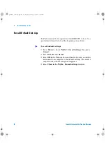
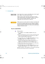
Agilent Technologies OmniBER J7230A Скачать руководство пользователя страница 63

Performance Tests

3

Installation and Verification Manual

61

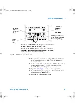
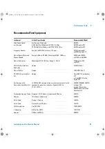
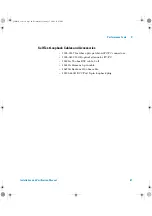
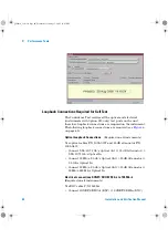
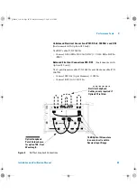
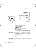
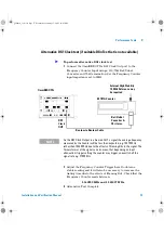
Self Test Loopback Cables and Accessories

 1005-0337 1m fiber optic patchcord FC/PC connectors.

 1005-0433 15 dB optical attenuator FC/PC.

 15525A 75 ohm BNC cable, 2 off.

 15512A Siemens 3-pin cable. 

 15670A Bantam 110 ohm cable. 

 J2125-65011 DCC Port 9-pin loopback plug.

panther3_iv.book Page 61 Wednesday, January 15, 2003 12:03 PM

Содержание OmniBER J7230A

Страница 1: ...Agilent J7230A OmniBER OTN 10 Gb s communications performance analyzer G 709 Verification Manual Installation and...

Страница 2: ...sdh_Lynx2 book Page 148 Wednesday April 17 2002 12 49 PM...

Страница 3: ...Agilent Technologies Agilent J7230A OmniBER OTN Installation and Verification Manual panther3_iv book Page 1 Wednesday January 15 2003 12 03 PM...

Страница 4: ...If software is for use in the performance of a U S Government prime contract or subcon tract Software is delivered and licensed as Commercial computer software as defined in DFAR 252 227 7014 June 199...

Страница 5: ...allation Getting Started This chapter provides general information on how to install and connect up the instrument 3 Performance Tests This chapter details the procedures to test the performance of th...

Страница 6: ...Menu Items Menu items appear in text in bold with the greater than symbol separating each menu level For example if you are instructed to choose Errors and Alarms from the Test Functions menu it appea...

Страница 7: ...ems When Making Measurements 26 Operators Maintenance 27 Statement of Compliance 29 Electromagnetic Compatibility 30 Declaration of Conformity 30 2 Installation Getting Started Preparation 32 Initial...

Страница 8: ...on of the Performance Self Test 61 Loopback Connections Required for Self Test 62 How to run the Self Test 64 What to do if the Self Test fails 65 Internal Reference Clock Accuracy 66 Alternative DS1...

Страница 9: ...and Output Level Characteristics 112 Performance Test Record 139 4 Self Test Overview Description of the Self Test 148 List of Self Tests 149 Loopback Connections Required for Self Test 151 How to Run...

Страница 10: ...8 Installation and Verification Manual panther3_iv book Page 8 Wednesday January 15 2003 12 03 PM...

Страница 11: ...21 Additional Precautions for Service Engineers 24 Avoiding Problems When Making Measurements 26 Operators Maintenance 27 Statement of Compliance 30 This chapter provides a brief description of the p...

Страница 12: ...d 2 66 Gb s SONET SDH plus PDH DSn test at all rates from 1 5Mb s to 10Gb s Generation of mixed mappings Simultaneous all channel testing up to 192 STSs AUs Comprehensive OTN SONET SDH overhead testin...

Страница 13: ...Optical Interfaces on page 12 Mixed Mappings on page 13 Optical Connectors product options on page 13 Alternative Optical Connectors available accessories on page 13 Other Options on page 13 Accessor...

Страница 14: ...Mb s to 2 5 Gb s not required J7230A 100 All rates up to 2 5 Gb s must be ordered with option J7230A 111 J7230A 101 Select one wavelength option for optical interfaces up to 2 66 Gb s 1310 nm optical...

Страница 15: ...Other Options Certificate of Calibration Option UK6 Calibration certificate with test data Warranty and Service Plans Adds Mixed mappings option Firmware only option that adds mixed mappings plus STS...

Страница 16: ...or access to Agilent Product information and sales service contacts please visit http www agilent com Accessories Carrying Cases J7266A Hard transit case for J7230A option 004 Optical Adapters and Cab...

Страница 17: ...ning as specified in the Agilent Operating and Service Manuals 5 Consumables such as paper disks magnetic tapes ribbons inks pens gases solvents columns syringes lamps septa needles filters frits fuse...

Страница 18: ...The serial number plate has a two letter reference denoting country of origin GB Great Britain and an eight digit serial number The serial number is unique to each instrument and should be quoted in...

Страница 19: ...ration or servicing If the instrument is being returned to Agilent for servicing attach a tag indicating the type of service required return address model number and full serial number In any correspo...

Страница 20: ...pound test material is adequate Use a layer of shock absorbing material 70 to 100 mm 3 to 4 inch thick around all sides of the instrument to provide firm cushioning and prevent movement inside the co...

Страница 21: ...ent Technologies assumes no liability for the customer s failure to comply with these requirements In particular the operator should note the following safety information Safety Symbols on page 20 Ope...

Страница 22: ...frame Alternating current AC Direct current DC Indicates hazardous voltages WARNING Warning denotes a hazard It calls attention to a procedure which if not correctly performed or adhered to could resu...

Страница 23: ...r your protection review all laser information given in this manual before installing or using the instrument CAUTION When connecting or disconnecting ensure that you are grounded or make contact with...

Страница 24: ...ce under test before connecting to any of the instrument s Optical Out connectors When connecting to the Optical In ports ensure the power level never exceeds the maximum stated limit for that port Al...

Страница 25: ...d also the receiver input ports Check for Status messages on the instrument display warning of overload conditions On the connector panel the following output input power level information is printed...

Страница 26: ...ice personnel must not attempt internal service or adjustment unless another person capable of rendering first aid and resuscitation is present Review Safety Precautions on page 19 ESD Precautions The...

Страница 27: ...irs Keep body movement to a minimum Agilent recommends that you use a controlled static workstation Avoid touching any components or edge connectors When you install the assembly keep one hand in cont...

Страница 28: ...ipment is not in a position where people will disturb the connecting fibers 4 Ensure that all fiber connections are clean and dirt free Use a fiberscope to measure the cleanliness of a unpowered fiber...

Страница 29: ...from the Power Line or switch off the laser transmitter before commencing this cleaning procedure WARNING No operator serviceable parts inside Refer servicing to qualified personnel To prevent electri...

Страница 30: ...sing a new piece of cleaning paper each time 6 Use a blow brush or compressed air to remove any particles of cleaning paper which may be present 7 These procedures also apply to any Optical patch cord...

Страница 31: ...ition and orientation Clean the bulkhead connectors as in step 2 and clean the inside threads of the SMA link taking care not to bend damage the center connector pin 4 Carefully refit the link taking...

Страница 32: ...condition The CE mark shows that the product complies with all relevant European legal Directives This is a symbol of an Industrial Scientific and Medical Group 1 Class A product This ISM device comp...

Страница 33: ...mity assessment requirements have been met using the technical Construction file route to compliance using EMC test specifications EN 55011 1991 Group 1 Class A and EN 50082 1 1992 In order to preserv...

Страница 34: ...32 Installation and Verification Manual 1 Introduction panther3_iv book Page 32 Wednesday January 15 2003 12 03 PM...

Страница 35: ...livery 41 Side Panel Connectors 49 Connectors on Instrument Rear Panel 55 Instrument Reboot Cold Start 55 This chapter provides general information on how to install and connect up the instrument and...

Страница 36: ...ation Checks on Delivery on page 41 notify the nearest Agilent office If the shipping container is also damaged or the cushioning material shows signs of stress notify the carrier as well as the neare...

Страница 37: ...VA There are no customer replaceable fuses in the instrument CAUTION This instrument is designed for use in Installation Category II and Pollution Degree 2 per IEC 61010 1 and IEC 60664 respectively V...

Страница 38: ...rd The mains plug shall only be inserted in a socket outlet provided with a protective earth contact Any interruption of the protective conductor inside or outside of the instrument is likely to make...

Страница 39: ...ch an instance to ground the instrument to an assured earth terminal The external protective earth terminal is on the rear of the instrument b If this instrument is to be energized via an auto transfo...

Страница 40: ...t To remove them gently lever them off When transporting the instrument always replace both covers to protect the instrument connectors and display Useful Information When Requesting Support When cont...

Страница 41: ...ructions given with the shelf 2 Fit captive nuts 4 off supplied to rack uprights 3 Place instrument on shelf 4 Connect power cord and GP IB cable if required before sliding the instrument into its fin...

Страница 42: ...rification Manual 2 Installation Getting Started 5 Fit the screws 4 off supplied through the flanges into the captive nuts and tighten to a torque setting of 2 Nm panther3_iv book Page 40 Wednesday Ja...

Страница 43: ...ON located beside power inlet 3 The fans should start and after a few seconds the display will initialize and indicate the following Starting Instrument Please wait The Agilent Technologies splash sc...

Страница 44: ...ectors from the ends of Patch Cord and Attenuator before fitting and make sure the white exposed ends are not touched by fingers or otherwise become contaminated When making connections ensure full lo...

Страница 45: ...roperly located before tightening WARNING Always ensure Optical Output Laser LEDs beside ports are OFF while making changing optical connections Also refer to Laser Warnings and Cautions on page 21 To...

Страница 46: ...rument at OC 192 instead Check the laser LED is illuminated at the 9 95 10 71 Gb s Output Port on the OmniBER OTN s connector panel 3 Press Menu choose Tx Rx Coupling then press Select Choose Copy Tx...

Страница 47: ...ransmitter Settings Signal Mode to SONET Signal Rate to OC 192 8 Check the laser LED is illuminated at the 9 95 10 71 Gb s Output Port on the OmniBER OTN s connector panel 9 Repeat step 4 to step 6 to...

Страница 48: ...to confirm correct operation 17 Press Window key to highlight the Transmitter Settings page and set the Laser to OFF 18 If the instrument has a single Receiver port covering the range 52 Mb s to 2 66...

Страница 49: ...the Transmitter Settings window and set the Laser to OFF 24 Disconnect all loopback connections Figure 5 622 Mb s Loopback Connection iii 15 dB Optical Attenuator to ensure level is within Receiver I...

Страница 50: ...ower then press Select Check the Received signal level is in the Green BER measurement power range 4 Ensure all optical connections are clean and fully connected with no sharp bends or twists in the o...

Страница 51: ...see table below for a 52 Mb s to 2 66 Gb s optical output Nominal wavelength is 1310 nm Power output is 5 to 0 dBm 52 Mb s 2 66 Gb s 1550 nm Selectable optical connector see table below for a 52 Mb s...

Страница 52: ...C 12 STM 4 and OC 48 STM 16 OTU1 signals is 28 to 8 dBm 9 95 10 71 Gb s Selectable optical connector see table below for 9 95 10 71 Gb s OC 192 STM 64 OTU2 optical input signals Wavelength 1290 to 156...

Страница 53: ...t Generated relative to the selected transmit reference clock DS1 Clock Out Bantam 100 ohm nominal connector for a DS1 BITS clock reference output Generated relative to the selected transmit reference...

Страница 54: ...er equipment Input Sensitivity 200 mV over a common mode input voltage range from 0 3V to 5 5V Output Level Logic 1 2 3 V typical Logic 0 0 8 V typical Electrical Test Ports SONET SDH Out BNC 75 ohm u...

Страница 55: ...DS1 Drop signal output DS1 In Bantam 100 ohm balanced connector for a DS1 Receive or DS1 Insert signal input 2 140 Mb s DS3 Out BNC 75 ohm unbalanced connector for E1 E2 E3 E4 DS3 transmit or E1 E3 E4...

Страница 56: ...Protocol None and Xon Xoff Speed 300 600 1200 1800 2400 4800 9600 19200 baud Parity Odd Even 1s 0s Stop Bits 1 2 Data Length 7 bits VGA Connector for displaying contents of instrument screen on an ext...

Страница 57: ...ent to be remotely controlled via the GPIB control bus External Protective Earth Connect an external earth connection to the instrument at this point AC Power Connect the instrument power cord here an...

Страница 58: ...d wait a few seconds 2 Switch the instrument on and as the instrument boots up look carefully at the display 3 Wait for the Starting instrument text to be displayed After a few seconds start to repeat...

Страница 59: ...nce Self Test 63 Internal Reference Clock Accuracy 68 External Clock Reference Inputs and Clock Reference Output 74 Optical Pulse Mask and Output Characteristics 81 Optical Receiver Sensitivity Optica...

Страница 60: ...re those typically used in Agilent Service Centers Where appropriate alternative models are also listed Performance Test Record The results of the Performance Tests may be recorded in the Performance...

Страница 61: ...n 100 or 8157A FC PC Optical Interface Connector Unique 81000FI Qty 4 Optical Cables Unique 1005 0337 Qty 2 PDH DSn Structured Test Set Unique OmniBER 718 with option 012 or OmniBER 719 with option 01...

Страница 62: ...nual 3 Performance Tests Cable SMA to SMA 8120 4948 Balanced Unbalanced Converter 110 balanced 75 Unbalanced nominal 15508B Instrument Critical Specification Recommended Model panther3_iv book Page 60...

Страница 63: ...Accessories 1005 0337 1m fiber optic patchcord FC PC connectors 1005 0433 15 dB optical attenuator FC PC 15525A 75 ohm BNC cable 2 off 15512A Siemens 3 pin cable 15670A Bantam 110 ohm cable J2125 6501...

Страница 64: ...est 1 Press Menu choose Tx Rx Stored Settings then press Select 2 Select Default then Recall 3 Select OK in the Warning box and then wait a few seconds for instrument to reconfigure to the default set...

Страница 65: ...elf Test How to run the Self Test What to do if the Self Test fails Description of the Performance Self Test The Self Test comprises of a selection of tests covering different areas of hardware in the...

Страница 66: ...Loopback Connections Required on all instruments Use optical cables P N 1005 0337 and 15 dB attenuator P N 1005 0433 Connect 9 95 10 71 Gb s Optical Out 15 dB Attenuator 9 95 10 71 Gb s Optical In Con...

Страница 67: ...nts with Option 012 only Use 3 pin Siemens cable P N 15512A and Bantam cable P N 15670A Connect 2M Out 3 pin Siemens 2M In Connect DS1 Out DS1 In Figure 6 Self Test Loopback Connections jlkjkljkljl kk...

Страница 68: ...uency Measurement Choose START to begin the test Further information on the Self Test can be obtained in the Self Test Overview section at the rear of this manual NOTE Some instruments have a single c...

Страница 69: ...onnections are in place 2 Be suspicious of any optical interface failures and if necessary clean all optical connections with a recognized cleaning kit before retrying the Self Test 3 If the problem p...

Страница 70: ...Frequency Counter is provided for the DS1 check if a suitable DSn Test Set is not available However in this case it should be noted that as this signal is a Framed All 1s Ternary signal the expected r...

Страница 71: ...matching pad set the input impedance to 50 Alternatively a 75 termination can be used with the input impedance set to 1M Frequency Counter Agilent 53181A Option 010 015 see Note DSn Test Set Agilent 3...

Страница 72: ...lso connect an External 10 MHz Reference signal to the Test Set 10M CLOCK Input port External High Stability 10 MHz Reference may be required Matching pad and or termination 2 MHz Clock OUT 75 UnBal 5...

Страница 73: ...37718C with Optn 012 Bantam to Bantam Cable DS1 Clock OUT to DS1 Data Input step 10 Loop DS1 Tx Rx OUT IN External 10 MHz Reference to Clock Timing I P NOTE This ensures the Test Set transmitter gene...

Страница 74: ...Clock Out port to the Test Set DS1 Receive port using the Bantam to Bantam cable 11 Check there are no Alarms Errors indicated by the Test Set Receiver 12 Set the Test Set to display the Frequency Off...

Страница 75: ...ter reads between 1 540993 MHz and 1 541007 MHz 3 Alternative Test Complete To perform alternative DS1 clock test NOTE As the DS1 Clock Output is a Framed All 1 s signal the average frequency measured...

Страница 76: ...external Clock source Clock Rate Description 2 048 Mb s MTS Accepts timing reference as per ITU T G 703 1998 2 048 MHz Clock Accepts timing reference as per ITU T G 703 1998 1 544 Mb s BITS Accepts DS...

Страница 77: ...he input impedance to 50 Alternatively a 75 termination can be used with the input impedance set to 1M Connect the Counter rear panel 10 MHz Reference Output to the PDH DSn Test Set external 10M CLOCK...

Страница 78: ...Counter Trigger Level to obtain a stable reading and check that the Frequency Counter reads between 2 047999999 MHz and 2 048000001 MHz 7 Confirm that the OmniBER OTN is locked to the External signal...

Страница 79: ...diagram below 12 Change the OmniBER OTN External Clock Format setting to 2 Mb s Data 13 Change the 2 MHz CLOCK OUT connection at the PDH DSn Test Set to connect the Transmit 2 Mb s DATA out BNC to th...

Страница 80: ...d remove the Test Set to OmniBER OTN BNC to BNC signal connection Connect a Balanced 3 pin Siemens cable between the Test Set Data OUT 3 pin port and OmniBER OTN CLOCK IN 3 pin port 19 Change the Test...

Страница 81: ...ct the OmniBER OTN s DS1 Clock Out port to the Test Set DS1 Receiver IN using a Bantam cable 25 Set the PDH DSn Test Set as follows TRANSMIT RECEIVE settings to COUPLED SIGNAL to DS1 rate CLOCK to INT...

Страница 82: ...27 Set the Test Set to Frequency Measurement Results and check that the displayed frequency is between 1543999 Hz and 1544001Hz 28 Confirm that the OmniBER OTN is locked to the External signal by dis...

Страница 83: ...Ratio are also measured using the oscilloscope Optical Output Power 1310 nm 1550 nm 2 66 Gb s 1550 nm 9 95 10 71 Gb s 1550 nm 9 95 10 71 Gb s 5 to 0 dBm 2 to 3 dBm 1 to 1 dBm version 1 5 to 1 dBm vers...

Страница 84: ...g in Agilent Infinium 86105A option 202 Optical Plug in Optical Attenuator Agilent 8156A Optical Patch Cord s Agilent PN 1005 0337 BNC m to SMA f Adapter Agilent E9632A SMA m to SMA m cable Agilent PN...

Страница 85: ...tenuation see Note Also connect the TX Eye Clock 52 Mb 2 5 Gb s to the oscilloscope Trigger input NOTE Optical signal should be attenuated to ensure specified maximum input for 86103A 4 dBm is not exc...

Страница 86: ...k Test Select Open Mask and open the STM000_OC1 msk 8 Select oscilloscope Autoscale and allow the oscilloscope to find signal and trigger inputs 86100A Optical Oscilloscope TX Eye Clock Optical Output...

Страница 87: ...tter Settings then press Select Select the Physical tab Set the Signal Rate to OC3 13 Select Eye Mask Mode Mask Test Select Filter and ensure it is set to OC 3 156Mb s ON 14 Select Open Mask and open...

Страница 88: ...nsmitter Settings then press Select Select the Physical tab Set the Signal Rate to OC12 20 Select Eye Mask Mode Mask Test Select Filter and set it to OC 12 622Mb s ON 21 Select Open Mask and open the...

Страница 89: ...lect Select the Physical tab Set the Signal Mode to SONET and the Signal Rate to OC48 Set Laser to OFF 27 Remove the Attenuator from the Setup and connect the 2 5 Gb s Optical Out Port 1310 1550 nm di...

Страница 90: ...OC 48 2 488Gb s ON 30 Set all other oscilloscope channels off 31 Select Eye Mask Mode Mask Test Select Open Mask and open the STM016_OC48 msk 32 Select oscilloscope Autoscale and allow the oscilloscop...

Страница 91: ...for 1310 nm 2 dBm to 3 dBm for 1550 nm 36 Check the Extinction Ratio is greater than 8 2 dB and record the measured value OC 48 STM 16 Eye Mask NOTE Ensure Vertical Calibration and Extinction Ratio Ca...

Страница 92: ...or 51 2 66 Gb s repeat step 1 through step 38 for the 1550 nm Output and use 1550 nm settings as appropriate for oscilloscope Channel inputs 9 95 Gb s and 10 71 Gb s Optical Output Checks 1 Press Menu...

Страница 93: ...ect the connect the TX Eye Clock 9 95 10 71 Gb s to the oscilloscope Trigger input as shown 4 Set the OmniBER OTN Laser to ON 5 On the oscilloscope select Setup Channel 3 Advanced settings Set it to t...

Страница 94: ...verage Power in dBm and Extinction Ratio 10 Check the Average Optical Power is between 1 to 1 dBm for version 1 optics OR 5 to 1 dBm for version 2 To determine if the instrument has version 1 or versi...

Страница 95: ...below Press Menu choose Tx Rx Transmitter Settings then press Select Select the Physical tab Set the Signal Mode to OTN and the Signal Rate to OTU 2 OC 192 STM 64 Eye Mask To test the 10 71 Gb s OTU2...

Страница 96: ...Measure mode and setup to measure the Average Power in dBm and Extinction Ratio 19 Check the Average Optical Power is between 1 to 1 dBm for version 1 optics OR 5 to 1 dBm for version 2 Check the Ext...

Страница 97: ...Performance Tests 3 Installation and Verification Manual 95 OTU 2 Eye Mask panther3_iv book Page 95 Wednesday January 15 2003 12 03 PM...

Страница 98: ...b s 2 5 Gb s 2 66 Gb s 9 95 Gb s 10 71 Gb s 10 dBm 9 dBm 9 dBm 9 dBm 10 dBm version 1 1 dBm version 2 Note 1 52 Mb s 2 66 Gb s for BER 1 x 10 10 input signal extinction ratio 8 2 dB 9 95 Gb s 10 71 Gb...

Страница 99: ...s minimum laser extinction ratio specification A table is provided at the end of these tests to check the typical additional receiver sensitivity expected against the extinction ratio of the laser use...

Страница 100: ...ower Meter Sensor Module Agilent 81633A Optical Attenuator Agilent 8156A FC PC Connector Interface qty 4 Agilent 81000FI Optical Cables qty 2 Agilent PN 1005 0337 WARNING Safety precautions must be ob...

Страница 101: ...Set the Optical Attenuator to ATTEN 15 dB WAVELENGTH 1310 nm or 1550 nm depending on wavelength used Optical Out 8156A Optical Attenuator 8163 81633A Optical Power Meter step 6 and 20 Depending on TX...

Страница 102: ...elect the Physical tab Set the Signal Mode to SONET and Signal Rate to OC1 Wavelength 1310 nm or if this is not fitted select 1550 nm Ensure the Laser is set to ON Check the laser LED is illuminated a...

Страница 103: ...rm no errors have been detected 10 Add more attenuation by increasing the Optical Attenuator setting to find the point just before the occurrence of errors This can be done by observing the Errors LED...

Страница 104: ...Smart Test choose Shortcuts Frequency Measurement then press Select The OmniBER OTN now displays the received frequency results Check that the frequency measurement reads between 51 83999 and 51 8400...

Страница 105: ...Repeat step 4 through step 15 substituting SIGNAL RATE OC 3 in step 5 17 Set the OmniBER OTN Transmitter to provide OC 12 output with PRBS bulk payload as follows Press Menu choose Tx Rx Transmitter S...

Страница 106: ...typically this will be at least 1 dB Press Run Stop to stop measurement 23 Re set the Optical Attenuator to the setting noted in step 18 providing 28 dBm output Set the OmniBER OTN s Receiver to disp...

Страница 107: ...dBm 1 Press Menu choose Tx Rx Stored Settings then press Select Select Default then Recall 2 Connect the test setup as shown below depending on wavelengths installed 3 Set the Optical Attenuator to AT...

Страница 108: ...ted at the selected Output Port 5 Adjust the Optical Attenuator to obtain a reading of 28 dBm on the Power Meter that is the Receiver minimum sensitivity for 2 5 Gb s rate Take note of the Attenuator...

Страница 109: ...ck that the frequency measurement reads between 2488 3199 MHz and 2488 3201 MHz 11 Reduce the Optical Attenuator setting by a further 19 dB and check the Receiver Optical Power result is between 11 dB...

Страница 110: ...st choose Shortcuts Trouble Scan then press Select Press Run Stop to begin measurement After 1 minute check that No Trouble is displayed in the Results window to confirm no errors have been detected 2...

Страница 111: ...the Results window to confirm no errors have been detected Press Run Stop to stop measurement 24 Disable the Optical Attenuator then disconnect the Optical signal from the OmniBER OTN Optical IN port...

Страница 112: ...cal Attenuator between the Power Meter and the OmniBER OTN s Optical Out port ensure that all connections are tight and that the cable has no twists 4 Set the OmniBER OTN Transmitter to provide OC 192...

Страница 113: ...Attenuator to Enable 7 Set the OmniBER OTN to TX RX Coupled Mode 8 Press Smart Test choose Shortcuts Trouble Scan then press Select Press Run Stop to begin measurement After 1 minute check that No Tr...

Страница 114: ...and all connections are tight with no twists in the optical cable Set the Optical Attenuator to Enable 14 Ensure the OmniBER OTN to TX RX Coupled Mode 15 Press Smart Test choose Shortcuts Trouble Scan...

Страница 115: ...specification The table below gives correction factors for a range ER values to check the additional Receiver sensitivity measured in tests Using the extinction ratio results from the Optical Pulse Ma...

Страница 116: ...2 1993 DS1 LO As DSX 1 with 655 ft ABAM cable DS3 HI 0 9 V pk nominal DSX 3 560 mV pk nominal Fits Mask T1 102 1993 DS3 900 330mV pl nominal 2 Mb s Balanced 3 00 V pk nominal As per ITU rec G 703 2 Mb...

Страница 117: ...e 54810A with Option 100 Communication Mask Kit E2625A Patch Cable 15512A Siemens 3 pin Patch Cable 15670A Bantam 110 ohm Adapter E2621A Termination Adapter Probe NOTE This performance test uses the I...

Страница 118: ...4 Load the DS1_ANSI msk test mask and run the mask test Check the Positive and Negative pulses are within the mask see examples Bal Unbal Adapter 54810A Oscilloscope OmniBER OTN CH1 E2621A DS1 Balance...

Страница 119: ...udes are between 2 4 3 6V pk 6 Set the instrument Output Level to DS 1 LO and check that the Pulse Output Amplitude decreases by approximately 20 and pulse shape has slower rise fall edges DSX 1 Posit...

Страница 120: ...et the Signal Rate to 2Mb s Termination 120 ohm Bal 3 Connect the 2 Mb s BAL OUT port to the Oscilloscope CHAN 1 using the E2621A Termination Adapter Probe set probe switch to 120 NOTE The DS1 LO Puls...

Страница 121: ...ive and Negative pulses are within the mask see examples Adapter 54810A Oscilloscope OmniBER OTN CH1 2 Mb s Balanced Output 3 pin Siemens cable E2621A 2 Mb s Bal OUT Set to 120 NOTE To test Negative p...

Страница 122: ...sts 1 Recall the OmniBER OTN s default settings as shown on Recall Default Settings on page 62 2M Balanced Positive Pulse 2M Balanced Negative Pulse To test the 2 Mb s unbalanced output pulse mask pan...

Страница 123: ...set the Signal Rate to 2Mb s Termination 75 ohms Unbal 3 Connect the 2 Mb s BAL OUT port to the Oscilloscope CHAN 1 using the E2622A Termination Adapter Probe Adapter 54810A Oscilloscope OmniBER OTN...

Страница 124: ...2Mb_ITU_75 msk test mask and check the Positive and Negative pulses are within the mask see examples NOTE To test Negative pulse set the Scope Mask Test Set up panel to Invert Mask 2M Unbalanced Posi...

Страница 125: ...etting as shown on Recall Default Settings on page 62 2 Press Menu select Tx Rx Transmitter Settings and set the Signal Mode to PDH DSn Now set the Signal Rate to 8 Mb s 2M Unbalanced Negative Pulse T...

Страница 126: ...Probe 4 Load the 8Mb_ITU msk test mask and check the Positive and Negative pulses are within the mask see examples Adapter 54810A Oscilloscope OmniBER OTN CH1 8 Mb s Output BNC to BNC cable E2622A 75...

Страница 127: ...al 125 1 Recall the OmniBER OTN s default setting as shown on Recall Default Settings on page 62 8M Unbalanced Positive Pulse 8M Unbalanced Negative Pulse To test the 34 Mb s output pulse mask panther...

Страница 128: ...Signal Mode to PDH DSn Now set the Signal Rate to 34 Mb s 3 Connect the 34 Mb s OUT port to the Oscilloscope CHAN 1 using the E2622A Termination Adapter Probe Adapter 54810A Oscilloscope OmniBER OTN C...

Страница 129: ...34Mb_ITU msk test mask and check the Positive and Negative pulses are within the mask see examples NOTE To test Negative pulse set the Scope Mask Test Set up panel to Invert Mask 34M Unbalanced Posit...

Страница 130: ...setting as shown on Recall Default Settings on page 62 2 Press Menu select Tx Rx Transmitter Settings and set the Signal Mode to PDH DSn Now set the Signal Rate to DS3 34M Unbalanced Negative Pulse T...

Страница 131: ...r Probe 4 Load the DS3_ANSI msk test mask and check the Positive and Negative pulses are within the mask see examples Adapter 54810A Oscilloscope OmniBER OTN CH1 DS3 Output BNC to BNC cable E2622A 75...

Страница 132: ...formance Tests 1 Recall the OmniBER OTN s default setting as shown on Recall Default Settings on page 62 DSX 3 Positive Pulse DSX 3 Negative Pulse To test the 140 Mb s output pulse mask panther3_iv bo...

Страница 133: ...l Mode to PDH DSn Now set the Signal Rate to 140 Mb s 3 Connect the 140 Mb s OUT port to the Oscilloscope CHAN 1 using the E2622A Termination Adapter Probe Adapter 54810A Oscilloscope OmniBER OTN CH1...

Страница 134: ...ts 4 Load the 140Mb_ITU_0 msk 140Mb_ITU_1 msk and 140Mb_ITU_1_INV msk test masks and check each of the pulses are within the mask see examples 140Mb s All Zeros Mask Test 140Mb s All Ones Mask Test pa...

Страница 135: ...l Default Settings on page 62 2 Press Menu select Tx Rx Transmitter Settings and set the Signal Mode to SONET Now set the Signal Rate to STS 1 and set the Output Level to STSX 1 140Mb s All Ones inver...

Страница 136: ...ck the eye meets the mask See examples Adapter 54810A Oscilloscope OmniBER OTN CH1 STS 1 STM 0e Output BNC to BNC cable E2622A 75 50 STS 1 STM 0e Output NOTE It may be necessary to use Manual settings...

Страница 137: ...Performance Tests 3 Installation and Verification Manual 135 STSX 1 Mask Test panther3_iv book Page 135 Wednesday January 15 2003 12 03 PM...

Страница 138: ...rmance Tests 5 Load the STS1_ANSI_PULSE msk test mask and check the positive and negative pulses meet the mask see examples STSX 1 Positive Pulse Mask Test STSX 1 Negative Pulse Mask Test panther3_iv...

Страница 139: ...ttings on page 62 2 Press Menu select Tx Rx Transmitter Settings and set the Signal Mode to SONET Now set the Signal Rate to STS 3 3 Connect the 155 Mb s OUT port to the Oscilloscope CHAN 1 using the...

Страница 140: ...ple 5 Press Menu select Tx Rx Transmitter settings and set the Signal Mode to SDH Now set the Signal Rate to STM 1 and Interface to Electrical Adapter 54810A Oscilloscope OmniBER OTN CH1 STS 3 STM 1e...

Страница 141: ...k the zero pulses are within the mask See examples 7 Also check the ones pulses normal inverted by loading and checking against the 155Mb_ITU_1 msk and 155_ITU_1_INV msk test masks see examples STM 1...

Страница 142: ...140 Installation and Verification Manual 3 Performance Tests STM 1 All Ones inverted Mask Test panther3_iv book Page 140 Wednesday January 15 2003 12 03 PM...

Страница 143: ...Self Test 66 step 5 Confidence Test Pass Fail 66 step 6 Frequency Measurement Pass Fail Internal Reference Clock Accuracy 70 step 4 2 MHz Clock OUT 2 0479908 MHz 2 0480092 MHz 72 step 13 DS1 Clock OUT...

Страница 144: ...sk and Output Characteristics Option 104 106 1310nm Optical Port 52 Mb s 2 66 Gb s 85 step 9 OC 1 STM 0 Mask Pass Fail 85 step 11 OC 1 STM 0 ER 8 2 dB N A 86 step 16 OC 3 STM 1 Mask Pass Fail 86 step...

Страница 145: ...33 OC 48 STM 16 Mask Pass Fail 89 step 35 OC 48 STM 16 PWR 2 dBm 3 dBm 89 step 36 OC 48 STM 16 ER 8 2 dB Pass Fail N A Option 111 87 step 37 step 33 OTU 1 Mask Pass Fail 87 step 37 step 35 OTU 1 PWR 5...

Страница 146: ...al Attenuation Typ 1 dB N A 101 step 11 30 dBm PWR meas 31 dBm 29 dBm 101 step 11 OC 1 STM 0 Frequency 51 83999 MHz 51 84001 MHz 103 step 12 10 dBm PWR meas 11 dBm 9 dBm 103 step 13 No Trouble Max Sen...

Страница 147: ...meas 10 dBm 8 dBm 104 step 25 No Trouble Max Sens Pass Fail 105 step 27 Power Meter check 9 5 8 5 Optical Receive Port 2 5 Gb s 106 step 4 Laser LED ON Pass Fail 106 step 5 Note Attenuator Setting N...

Страница 148: ...p 4 Laser LED ON Pass Fail 111 step 5 Note Attenuator Setting N A N A 111 step 8 No Trouble Min Sens Pass Fail 111 step 9 Additional Attenuation Typ 1 dB N A 111 step 10 14dBm PWR meas 15 5 dBm 12 5 d...

Страница 149: ...2 Mb s ITU 120 Mask Pass Fail page 122 step 4 2 Mb s ITU 75 Mask Pass Fail 8 Mb s Output Mask Tests page 124 step 4 8 Mb s ITU Mask Pass Fail 34 Mb s Output Mask Tests page 127 step 4 34 Mb s ITU Mask...

Страница 150: ...tallation and Verification Manual 3 Performance Tests page 139 step 6 155 Mb s ITU_0 Mask Pass Fail page 139 step 7 155 Mb s ITU_1s Mask Pass Fail panther3_iv book Page 148 Wednesday January 15 2003 1...

Страница 151: ...the Self Test Fails 162 The instrument Self Test consists of a number of tests and sub tests designed to verify the functionality of the instrument measurement and utility ports as well verify the ma...

Страница 152: ...n dependent Self Test can be run as one complete sequence or an individual test may be run If a failure occurs then a descriptive text message and Fail Code is returned An Error example is provided at...

Страница 153: ...single error 3 Optical Power Test This test checks both the data paths and the optical power measurement circuitry 4 DCC Add Drop Test The test checks the data paths associated with the DCC add drop h...

Страница 154: ...confidence test on the unbalanced electrical paths only 15 Confidence Test E1 Balanced Ports This test performs a confidence test on the E1 balanced port only 16 Confidence Test DS1 Balanced Ports Th...

Страница 155: ...B Attenuator 9 95 10 71 Gb s Optical In Connect 52 Mb s 2 5 Gb s Optical Out 15 dB Attenuator 2 5 Gb s Optical In Connect 52 Mb s 2 5 Gb s Optical Out 15 dB Attenuator 52 Mb s 622 Mb s Optical In Elec...

Страница 156: ...ded Ensure the recommended optical attenuation is present in all optical loopback connections as failure to do so could cause self test failure or damage to the optical receivers jlkjkljkljl kkkkkkkk...

Страница 157: ...onfidence Tests E1 Balanced Ports E Confidence Tests DS1 Balanced Ports F Optical Power Test A B C not required not required DCC Add Drop Test A not required E Frequency Test A B C D not required NOTE...

Страница 158: ...test in sequence The remaining test time to complete the tests is displayed on the right hand side of the Self Test page 5 If any sub test fails an error message and error code will be returned Up to...

Страница 159: ...d in sequence starting with the highest rate interface down to the lowest rate interface The actual number of sub tests run is dependent on the instrument options fitted for example single or dual wav...

Страница 160: ...1310 nm 7 Conf 155 Mb s 1550 nm 8 Conf 52 Mb s 1310 nm 9 Conf 52 Mb s 1550 nm 10 Conf 155 Mb s 11 Conf 52 Mb s 12 opt 012 only Conf E4 Unbal 13 opt 012 only Conf E3 Unbal 14 opt 012 only Conf E2 Unba...

Страница 161: ...er Sub Test Description 1 10 Gb s 1550nm 2 2 5 Gb s 1310 1550nm 3 622 Mb s 1310 1550nm Sub Test Number Sub Test Description 1 Performed at the maximum available DCC GCC channel rate Sub Test Number Su...

Страница 162: ...1550 nm Sub Test Number Sub Test Description 2 Conf 2 5 Gb s 1310 nm 3 Conf 2 5 Gb s 1550 nm 4 Conf 622 Mb s 1310 nm 5 Conf 622 Mb s 1550 nm 6 Conf 155 Mb s 1310 nm 7 Conf 155 Mb s 1550 nm 8 Conf 52...

Страница 163: ...Manual 161 Test 15 Confidence Test E1 Balanced Test 16 Confidence Test DS1 Balanced Sub Test Number Sub Test Description 16 Conf E1 Bal Sub Test Number Sub Test Description 18 Conf DS1 Bal panther3_i...

Страница 164: ...Checks to Confirm Correct Optical Loopback Make sure connectors are located in key notch of the port connectors to ensure full insertion Check Transmitter and Receiver are set to the same Signal Rate...

Страница 165: ...erminology The terminology used on the instrument display can be ETSI SDH or ANSI SONET Refer to the table given in this section for an explanation of equivalent SDH SONET terms panther3_iv book Page...

Страница 166: ...ra Office n STM n level Intermediate Reach IR L n 1 or L n 2 long haul LR long reach Low Order Path LP LO VT Path LP REI REI V M S P A P S Multiplexer Section MS Line Multiplexer Section Protection Au...

Страница 167: ...C DCC S Section Overhead SOH Transport Overhead TOH S n 1 or S n 2 short haul Short Reach SR SOH TOH STM m OC n STS n where m n 3 for m 1 STM 0 STS 1 STM 1 OC3c STS 3c STM 4 OC 12 STS 12 STM 16 OC 48...

Страница 168: ...ation for ATM Virtual Channel The context of VC must therefore be taken into account when converting between standards TUG3 VT Group 86 columns TU multiframe VT superframe TU PATH AIS VT AIS AIS V VC...

Страница 169: ...9 95 Gb s Optical Out port 49 DCC GCC Trigger port 51 DS1 Clock Input port 51 DS1 Clock Out port 51 external protective earth terminal 55 GPIB port 55 keyboard port 54 LAN 10M 100M port 54 mouse port...

Страница 170: ...192 STM 64 109 OC 48 STM 16 Rates 105 OTU 1 2 66 Gb s 107 OTU 2 10 71 Gb s Rate 112 Options certificate of calibration warranty service plans 13 guide 11 Original Packaging 17 OTN interfaces 12 OTU 1...

Страница 171: ...rm Test 157 Optical Power Measurement 159 Sub Tests Confidence Test 158 T Temperature 17 environment 34 35 Tips and Checks to Confirm Correct Optical Loopback 162 Transit Cases 17 Trigger port 51 V Ve...

Страница 172: ...170 Installation and Verification Manual panther3_iv book Page 170 Wednesday January 15 2003 12 03 PM...

Страница 173: ...sdh_Lynx2 book Page 148 Wednesday April 17 2002 12 49 PM...

Страница 174: ...In This Book This book contains installation information and methods for checking instrument specifications Verification of the OmniBER OTN Printed in U K 01 03 J7230 90035...

Отзывы: