Version 15.0
AF-5000 Series Pilot Guide
10
WARNING
It is possible for any instrument to fail and display inaccurate readings. Therefore, the pilot must
be able to recognize an instrument failure and must be proficient in operating the aircraft safely in
spite of an instrument failure. Contact the FAA or a local flight instructor if training is desired to be
proficient
. The ability for this product to detect a problem is directly related to the pilot’s ability to
program proper limits and the pilot’s interpretation and observation skills. The pilot must
understand the operation of this product before flying the aircraft. Do not allow anyone to operate
the aircraft that does not know the operation of this product. A copy of this manual must be kept
in the aircraft at all times.
Displays Are Synchronized
If you have multiple AF-5000 displays in your aircraft, actions such as setting BARO, BUGS, engaging the Autopilot, or
acknowledging warnings only need to be performed on one display (or control panel) and that action is synchronized
throughout the AF-5000 system. Some settings such as individual screen layout and map range level are deliberately
not
synchronized between multiple AF-5000 displays.
Buttons, Knobs and Touch Interface
User interaction takes place via the two upper side knobs, buttons integrated into the knobs, bottom knob joystick and
18 buttons along the bottom and side of the AF-5000
display’s bezel and via touch gestures on the display screen itself.
Data Logging
AF-5000 displays record and store flight information in several datalogs which can be exported for analysis by the
owner, and a high-resolution datalog which can is used by Dynon Avionics for troubleshooting.
Synthetic Vision (SVN)
When valid GPS data is available, and a high-resolution terrain database for the appropriate region is loaded, the PFD
features integrated Synthetic Vision. Synthetic Vision displays the terrain directly ahead of the aircraft. Terrain is
graphically represented in sectional chart color variations which represent topographical elevations and water features.
Terrain is textured with a subtle pattern to aid in identifying aircraft movement.
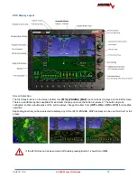
GPS Moving Map and VFR GPS Navigator
AF-5000 features a robust GPS moving map and VFR GPS navigator. Aviation and Obstacle data can be displayed, as well
as VFR and IFR enroute charts, procedure charts (plates), and airport diagrams. Go to
http://advanced-flight-
systems.com
to find links to the various sources of aviation / obstacle data and chart data.
Flight Data Modules
–
SV-ADAHRS-200, SV-ADAHRS-201, and SV-MAG-236
This guide uses SV-ADAHRS-20X to refer to both the SV-ADAHRS-200 and the SV-ADAHRS-201. The SV-ADAHRS-200 and
SV-ADAHRS-201 are identical in performance and are designed to work together as a redundant ADAHRS solution.
The primary flight instruments on your AF-5000 PFD are generated using a group of calibrated sensors built into the SV-
ADAHRS-20X ADAHRS module. All sensors are solid state
–
that is, there are no moving parts. These sensors include
accelerometers, which measure forces in all three directions; rotational rate sensors, which sense rotation about all
three axes; pressure transducers for measuring air data; and magnetometers on all three axes for measuring magnetic
heading. Due to the sensitivity of the SV=ADAHRS to magnetic interference, some aircraft installations are better served
by mounting the SV-ADAHRS-20X within the specified center of gravity box and installing an SV-MAG-236 Remote
Magnetometer well away from any dynamic magnetic interference
–
and possibly outside the center of gravity box
specified for the ADAHRS. If an SV-MAG-236 is installed,
its magnetometer
provides magnetic heading data to the
system, and data from the integrated magnetometer(s) in the SV-ADAHRS-20X are disregarded.
Table 2 describes which inputs and sensors are used within the ADAHRS module to generate the different displayed
instruments.
Содержание AF-5400
Страница 36: ...Version 15 0 AF 5000 Series Pilot Guide 36 Analog Instrument Page EFIS ANALOG AF 5400 SET EFIS ANALOG...
Страница 58: ...Version 15 0 AF 5000 Series Pilot Guide 58 Flowchart Pitch Axis IAS Hold Procedure...
Страница 60: ...Version 15 0 AF 5000 Series Pilot Guide 60 Altitude Capture Procedure Part 1 of 2 Part 2 of 2...
Страница 62: ...Version 15 0 AF 5000 Series Pilot Guide 62 Autopilot Settings Defaults...
Страница 73: ...Version 15 0 AF 5000 Series Pilot Guide 73 FREQ Tab RCNT Tab...
Страница 88: ...Version 15 0 AF 5000 Series Pilot Guide 88 VFR Sectional Full Screen Mode Split Screen Mode...
Страница 89: ...Version 15 0 AF 5000 Series Pilot Guide 89 IFR Low Altitude Chart Airport Diagrams...


