background image


44 

3.06 Opening MTC Files 


3.06.1 Opening a New File/Project 


When you launch MTC, a new blank 

Virtual Mat

 will appear with a new blank project opened.   At any time, 

another new project can be opened, in a new window, using any of the following: 


C

lick the “

+

” icon on the 

Tab 

bar    


Right click on a project tab on the

 Tab


Bar

 and select 

New

 from the menu 


Click on the 

New

 icon on the 

File

 toolbar   


Press 

Ctrl+N


Go to

 File>New.


3.06.2 Opening an Existing MTC File 


An existing file can be opened into MTC by using any of the following: 


Click on the 

Open

 icon on the 

File

 toolbar  


Right click on a project tab on the 

Tab


Bar

 and select 

Open

 from the menu 


Press 

Ctrl+O


Go to 

File>Open


Double click an MTC file in Windows Explorer (refer to 

Section 3.06.3

 for instructions on installing and 

using the 

MTC File Viewer


Double click an MTC file attached to an email 


Drag and drop an MTC file into a running instance of MTC 


Import from 

MTC Gallery

 (refer to 

Section 4.02

). 


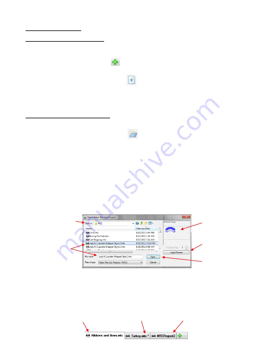
In all cases, a window will open where you can browse to locate the file you wish to open: 


There is also a 

Basic Shapes

 library available (Refer to 

Section 3.08

). Plus other file formats (such as .svg, 

.eps, and .ai) may be imported into MTC. Refer to 

Sections 4.01-4.08.


As you open new projects or existing files, the 

Tab Bar

 will show each project: 


Browse to locate folder 

A preview of the file 
shape(s) will appear 

Click here to open a window 
to display a larger preview 
of the file shape(s) 

Click on 

Open

 and the 

saved file will open as a new 
project 

Click on the file and 
it will appear under 

File name

This project has been saved 
using the name shown. 

This project has been saved using the 
name shown but the asterisk indicates 
that changes have been made since the 
file was last saved. 

This is a new project that 
hasn’t yet been saved. 

Содержание ACS-24UHF/Eagle

Страница 1: ...le zoomed in moving the mouse automatically scrolls the page up and down Search You can search by any word s in the manual Click on the Search icon enter the word s and all pages with that word or wor...

Страница 2: ...Most Common Mistakes Made by New Owners 21 Begin with Easy Materials and Easy Shapes 21 Record Your Successes 21 Use the Correct Blade for the Material You Are Cutting 21 Set the Blade Length Exposure...

Страница 3: ...ESIZING ROTATING SLANTING AND WARPING 58 Resizing 58 Rotating and Slanting 59 Warping 60 3 14 CHANGING COLOR TEXTURE AND LINE STYLE 60 Changing Color 60 Changing Texture 61 Removing a Texture 63 Chang...

Страница 4: ...Trace 105 6 03 5 Color Scans Trace 110 6 04 MANUAL TRACING 118 Importing an Image for Manual Tracing 119 Manual Tracing Using the B zier Curves and Straight Line Pen Tool 120 Flip Mirror and Weld to C...

Страница 5: ...ption 160 Corner Join Option 161 Inset Shadow 161 8 06 WELD TOOL 162 Designing a Balloon 162 Designing a Border 162 Designing a Wreath 163 8 07 BOOLEAN JOIN 164 Cutting One Shape from Another 164 8 08...

Страница 6: ...12 Applying Vinyl 213 10 04 FABRIC AND FELT 213 10 05 IRON ON TRANSFER 214 Types of Iron On Transfer 214 Cutting Iron On 214 Adhering Iron On 215 10 06 RHINESTONE TEMPLATES 215 Designing Rhinestone Pa...

Страница 7: ...upplier as soon as possible ACS 24UHF Cutter Cutting Mat Blade Holder Spray Adhesive for Mat Two blades 45 degree and 60 degree Bolt on Tables Testing Pen Holder with 2 pen inserts Screws and screwdri...

Страница 8: ...utter o TURN OFF the cutter when not in use 1 04 Parts Diagram Front Left Side Right Side Back Control Panel built into top on some models Blade Carriage Blade Holder Seat Bolt On Front Table Pinch Wh...

Страница 9: ...rned on Then the cutter will come to rest in the Online Mode Experiment with and buttons as shown 7 Offline Mode moves carriage to the left Online Mode increases cutting force 8 Offline Mode moves mat...

Страница 10: ...e Baud Rate based on the connection you are using Increases Decreases Traverse Velocity Up Speed Set to 200 if doing PNC applications Increases Decreases Baud Rate USB 57600 Serial 9600 Step 5 In Onli...

Страница 11: ...tion The blade must be carefully inserted into the blade holder Do this over a soft surface e g over a hand towel It s important to protect the fragile blade To install follow the numbered steps as sh...

Страница 12: ...tape to secure the material to the mat If you are cutting thin paper then you may want to experiment with lighter adhesives Use a plastic scraper an old credit card will suffice to scrape off any ran...

Страница 13: ...Upon completing the form a registration number will be provided This is your permanent registration number for the computers you own You can leave this window open until you get MTC installed or you...

Страница 14: ...onto another computer please go the same prior link and click on Recover Pin It s now time to connect the KNK to your computer Go to Section 1 10 Installing on a Mac There are three things to install...

Страница 15: ...right side of the cutter Connect your cutter to your computer using either of the following USB Connection Turn off the cutter and connect the USB cable to the right side of the cutter and into an av...

Страница 16: ...d to the far left side and left in the up position Assemble the pen holder as shown in Section 1 06 Make sure the pen will write by scribbling on scrap paper Then loosen the screw on the blade holder...

Страница 17: ...mat To open the cutting control window go to Cut Project With Klic N Kut Series A new window will open where you can locate your COM port assignment under the Serial Port menu Double click any of the...

Страница 18: ...post at the Klic N Kut Yahoo group mentioned on the first page If the test succeeded then try drawing your shape First note the following in the Controller window After making the appropriate settings...

Страница 19: ...is how Knife Point mode works If you want the image to draw where you have it on the Virtual Mat then you need to switch to WYSIWYG mode and use the laser to set the origin versus the tip of the pen...

Страница 20: ...20...

Страница 21: ...much force is being used for the material being cut Forget to set the Blade Offset before cutting Failure to do a test cut to make sure settings are optimal Not practicing enough with the test pen an...

Страница 22: ...s not nor scratch the layer below you have the perfect length Having the blade fully extended will never result in better cutting In fact it can cause skewing tearing of the material damage to the bla...

Страница 23: ...Number of Passes Based on the Material and Shapes Using correct cut settings is equally important as the type of blade blade length and blade height Refer to Sections 2 03 2 05 for details Keep the Cu...

Страница 24: ...uestions and get answers from other users dealers and Make The Cut experts Utilize these resources Main Klic N Kut Yahoo Group http groups yahoo com group Klic N Kut KNK Support Forum http knkusa com...

Страница 25: ...p 4 The movement within the Klic N Kut logo can be toggled on and off by left clicking on the logo 2 03 Force The cutting force also called pressure greatly affects the quality of the cut If the force...

Страница 26: ...an range from 75 120 Some Bazzill weaves may require multi pass to completely cut the cardstock This is not a function of pressure rather a function of the inconsistency in the cardstock itself Note t...

Страница 27: ...Blade Offset for most cutting with both the 45 o and the 60 o blades is 0 25 For the fabric blade an offset of 0 4 is recommended When drawing with a pen or engraving set the Blade Offset to 0 This se...

Страница 28: ...or Landscape modes for the Virtual Mat The shapes will cut in the same relative locations on the material Use the arrow on the Virtual Mat as a guide to the direction to insert the actual mat or mate...

Страница 29: ...t matches the material dimensions For example if you are cutting from an 8 5 x 11 sheet of cardstock then create a Virtual Mat with those same dimensions You can use either Portrait or Landscape mode...

Страница 30: ...BMP PNG etc will need to be pixel traced first so that cut lines are created Refer to Chapter 6 for tutorials on how to do the pixel tracing also called vectorizing Refer to Chapter 9 for tutorials o...

Страница 31: ...e might cut 7 15 16 x 8 1 32 Now this might be perfectly acceptable for the type of cutting you do Therefore it may not even be necessary to do this particular calibration However if you do want to ma...

Страница 32: ...the Klic N Kut Model menu A window will open Click on the Resolution tab and then click on another small wrench icon Make sure this is locked H will automatically change to 8 0 as well if Aspect Ratio...

Страница 33: ...then just repeat again If you need to be very precise and you cannot accurately measure the sides then you can also just slightly adjust the actual numbers themselves using this as a guide Click on sm...

Страница 34: ...34 Settings Form for Cutting Materials1 Material Type Material Brand or Source Blade Force Speed Blade Offset Passes Spacing Other Comments 1 2009 2013 Sandy McCauley All Rights Reserved...

Страница 35: ...c thicker nappy fabrics Fabric 140 400 3 2 N Heat n Bond applied first Felt Regular Fabric 100 3 2 Y Used sticky mat Felt Stiffened Blue 120 200 2 3 Y Foam Fun Foam from Michael s Blue 25 150 2 3 Y Gu...

Страница 36: ...ress well to the mat Styrene 02 Blue 120 250 2 2 Y Cut clean in 2 doesn t give perfect results when cutting intricate detail Tissue Paper Fabric 24 100 1 0 N Ironed tissue first carefully rolled onto...

Страница 37: ...creen Below is a screen shot of the main screen in MTC identifying toolbars bars and other important elements on the screen Note the specific names of the items shown as they will be referenced throug...

Страница 38: ...the Menu Bar When you first open MTC a popup may ask you if you want to open this window For details about the Lettering Delights function refer to the last part of Section 4 07 Not all of the functi...

Страница 39: ...ns in the software The following text boxes indicate the primary functions found in each of the Menu Bar choices Sel Properties Bar The Select Properties Bar displays the location and size of the curr...

Страница 40: ...ing which shapes to print or cut All shapes on a layer may be re colored hidden from view locked deleted and moved up or down Refer to Section 3 12 for details on using the Layer Bar Tab Bar In MTC op...

Страница 41: ...ll Locks are currently activated If you hover your mouse over one of the icons on a bar or toolbar or if you open one of the drop down menus from the Menu Bar the Status Bar typically provides additio...

Страница 42: ...tered and the mat configuration will look like the following depending on whether you then set orientation to Portrait or Landscape Scroll to desired Zoom level Select mat dimensions Choose from 8 mat...

Страница 43: ...ng Any of the following methods will allow you to zoom in and out in 10 increments from 20 to 1000 Hold down the Ctrl key while rolling the mouse wheel The zoom will center on where the mouse cursor i...

Страница 44: ...le Viewer Double click an MTC file attached to an email Drag and drop an MTC file into a running instance of MTC Import from MTC Gallery refer to Section 4 02 In all cases a window will open where you...

Страница 45: ...omputer and you ll want to make sure it shows your c drive Then click on OK After several minutes a new window will open Scroll down in the menu of this window and make sure Thumbnails is checked and...

Страница 46: ...various windows in which you ve made changes will then open in sequence with the option to save the changes or not or cancel the saving process for that file You can also turn on an auto saving optio...

Страница 47: ...ing To select a shape click anywhere within the bounding area or bounding box which is indicated by the rectangle appearing around the shape There are several ways to select more than one shape Select...

Страница 48: ...mall increments by pressing the arrow keys on the keyboard Further if you hold down the Ctrl key while pressing these arrows keys the shape will move in larger increments with each keystroke With a sh...

Страница 49: ...following to access the Delete by Area option Right click on the screen and choose Delete By Area from the menu Press Ctrl Shift R Go to Edit Delete by Area The Delete by Area window allows you to se...

Страница 50: ...ck on the Paste from Clipboard icon located on the File Toolbar Right click on the screen and select Paste Press Ctrl V Go to Edit Paste To Paste in Place shapes from the clipboard use any of the foll...

Страница 51: ...Duplicate Nested Duplicate Outlines and Inlines In the first example a scalloped circle is selected and the Nested Duplicate function accessed The following window opens with defaults settings shown a...

Страница 52: ...se with basic shapes such as circles or polygons Scaling by Width duplicate paths stay scaled to the original and the width will be changed according to the gap selected The resulting height may resul...

Страница 53: ...e or partial circle pattern To access Rotated Duplicate first select the shape s and then use either of the following Right click on the screen and select Duplicate Rotated Duplicate Go to Edit Duplic...

Страница 54: ...sibilities are unlimited with this magnificent feature Be sure to watch the video linked at the beginning of this section 3 11 Undo Redo Undo As with most Windows applications there is an Undo functio...

Страница 55: ...and to control what is sent to the cutter or printer This bar can be turned on and off under View on the Menu Bar Most likely you will want to have this bar showing at all times You do not have to wo...

Страница 56: ...and will also prevent any movement or resizing etc of those shapes Also any shapes that are hidden will not be sent to your cutter or to your printer Change the order of layers using the arrow icons M...

Страница 57: ...e not delete the layer move the layer to its own page using the Layer Options Menu at the bottom of the Layer Bar Click on the Delete Empty Layers icon to delete any layers that contain no shapes Clic...

Страница 58: ...nding on the current setting for Snap Position on the Virtual Mat the resizing will occur in increments matching that setting To freely resize the shape change Snap Position to No Snapping If you wish...

Страница 59: ...screen If you hold the Shift key while dragging one of the four corners the shape will be pinned in the diagonally opposite corner and will rotate around that corner If you hold the Ctrl key while dr...

Страница 60: ...the gridlines of the virtual mat in the background and without the bounding boxes around the shape s This was done to make the images appear clearer and less cluttered 3 14 Changing Color Texture and...

Страница 61: ...was already a texture open in your current project then the Choose Texture window opens In this window you have options to Tile the Texture fill a shape with a modified version of the texture Vertica...

Страница 62: ...e fills with the new customized texture Option 1 Select a texture already present in your project Option 2 Browse computer to locate folder and file containing texture you wish to use Settings for the...

Страница 63: ...hosen Here are two examples 3 15 Other Shape Manipulations Alignment There are eleven functions used to align shapes with one another After selecting two or more shapes these functions can be accessed...

Страница 64: ...e another Outer Alignment There are four different alignment functions used to align shapes to the outside edges Again with the shapes selected right click and go to Align and Space Align Right press...

Страница 65: ...ost shape of the group Edge Top aligns shapes along their bottom edge of the uppermost shape of the group Edge Bottom aligns shapes along their top edge of the lowermost shape of the group Right R ali...

Страница 66: ...pes is to hold the Ctrl key and drag the middle This same method can be used for vertical spacing as well The shapes also do not need to be the same You could equally space for example a star a letter...

Страница 67: ...67 Press Ctrl F Go to Edit Shape Magic Flip...

Страница 68: ...ges identified in the search will appear Optional Enter a Search Term that may have been used in the file name or description Select a Category from drop down list Select a particular User ID Select F...

Страница 69: ...pen allowing you to browse your computer to locate a subfolder and select the file you wish to import With SVG you can click on Large Preview to open a window displaying a much larger view than the th...

Страница 70: ...ort Click on Large Preview to better see the individual shapes or use Adobe Reader to view the pages in the same way you would view any PDF file MTC will only import AI files that are Version 9 or new...

Страница 71: ...rned on The Fuse N Weld option is needed to connect the many individual segments making up paths in GSD files The Render Metafiles function is use to identify embedded wmf and emf files used for print...

Страница 72: ...can choose to go to the Lettering Delights web site to purchase this particular product The shapes in that product package will then be available to download directly into MTC in the future when you l...

Страница 73: ...g ways Go to File Export and select from one of the available export options Right click on the screen and select Export Right click on the project tab on the Tab Bar and select Export from the menu T...

Страница 74: ...l dimensions of all shapes in the file is available From the Export options choose Sel as Project to MTC Gallery An identical window appears but the upload will include everything in the file includin...

Страница 75: ...raster For example 1 The image could be posted on a web site or blog 2 The image could be shared with a friend or a customer 3 The image could be used in a digital scrapbooking program Select the ima...

Страница 76: ...n on the File Toolbar to import the shapes at the original size Note the fill and stroke colors assigned in Illustrator will not be brought into MTC On some shapes duplicates can result during the con...

Страница 77: ...l be created on the Layer Bar and those shapes assigned to that new layer This may be faster and easier then copying and pasting everything to MTC and then trying to reassign same colored shapes to th...

Страница 78: ...down menu and then use your mouse scroll button to scroll through all of the fonts in the menu Make sure the Show Face option is marked if you want the font names to appear in the actual font If you a...

Страница 79: ...to worry Once a particular font is used to create text and that file is saved then that same font does not need to be re opened when opening that same file If you wish to open more than one font at a...

Страница 80: ...ertical text select Rotate Left in the Add Text Group window Then select the text created and rotate 90 0 Ctrl G Alignment options Begin typing to enter text into window Press Enter key to start new l...

Страница 81: ...be better choices If you inadvertently select the wrong option for your intended design not to worry You can use the Split function Ctrl P on the text after you close the Add Text Group window to Spl...

Страница 82: ...e actual positioning of the letters You may also want to check the text both with and without the Fill turned on which can be changed on the Virtual Mat tab You can also quickly overlap letters by sel...

Страница 83: ...and it will added at the location of the Caret refer to Section 4 01 Resize and arrange the dingbat shape as desired Also overlap the letters with each other as desired Then apply the Weld Ctrl W tool...

Страница 84: ...the text making sure the Split by Glyphs option is selected If you forget then use the Split function to break your text into individual letters The next step is to create the circle You can import a...

Страница 85: ...will rotate the text around the outside if desired so that the text begins in a circle location along the outside of the circle On the settings you drag with your mouse button remember to also use th...

Страница 86: ...on Accept the second half of the text is selected and again moved to the center of the circle while holding the Ctrl key Adjust the Vert Align and the Space settings to match what was used for the to...

Страница 87: ...can be welded or not And if not welded the letters can be Split by Glyphs or not With the title selected open the B zier Warp window using one of the following ways Click on the B zier Warp icon on t...

Страница 88: ...can be modified by dragging green blue and red handles points Increase Points to add more changes in the curve Uncheck Close Curve to create an open path Scroll these two settings to 25 to fit text ha...

Страница 89: ...d double click to add to the screen On the Virtual Mat settings tab on the Main Bar refer to Section 4 04 make sure you have Outline mode selected so that you will be able to see the rectangle and the...

Страница 90: ...J Right click on the screen and choose Shape Magic Join from the menu Go to Edit Shape Magic Join Now marquee select both the rectangle and the letters and bring up the Boolean Join menu using any of...

Страница 91: ...lbar and can be activated by first opening the Node Edit toolbar or pressing W and then clicking the icon or pressing F8 Zoom in close on the lettering so that you ll be able to see exactly where you...

Страница 92: ...gle lines curves only These fonts are useful when using a pen or engraving tool in your cutter or for designing single line rhinestone titles Refer to Section 8 12 for more information on the Rhinesto...

Страница 93: ...le in which little dots called nodes or points are connected to each another with paths either straight lines or curves Digital die cutters need those paths so that that they can communicate to the cu...

Страница 94: ...ages based on keywords Google Images also has filters at the top of the window under Search Tools to limit your search to black and white as well as to clipart or line drawings Use these filters 6 03...

Страница 95: ...ods Be adventurous in your tracing You can always go back and delete parts of a trace you don t like or duplicate tracings that are not as perfect as perhaps one of the others Chapter 7 contains metho...

Страница 96: ...her colors just like any other shapes The Threshold setting ranges from 1 255 Decrease this setting to add more distinction between colors and increase the number of individual paths recognized and tr...

Страница 97: ...e used to increase or decrease how tightly an image is traced Lower it to decrease the number of nodes and loosen the fit of the tracing Increase it to increase the nodes and create a more precise fit...

Страница 98: ...r Alpha Palette and Color options available this feature may not ever be something you need 6 03 2 Alpha Trace Method Use the Alpha Trace for PNG files with transparent backgrounds alpha channels To s...

Страница 99: ...hose settings As indicated in the screenshot the tracing could be used for vinyl cutting since vinyl is applied using transfer tape However let s say this is going to be a print and cut application in...

Страница 100: ...outline you want Mark the Texture Path box click on Apply Changes and the image appears on the screen ready for the print and cut process refer to Chapter 9 Threshold is increased to 240 Blackout Path...

Страница 101: ...Cut First turn off all of the colors by right clicking on the boxes A popup menu will appear which provides some options for which colors to have selected as well as how to sort them Begin by choosin...

Страница 102: ...re going to cut this as a paper piecing pattern or as a vinyl design perhaps you want to use the same color for the petals and for the center Thus clicking on that color followed by click on Apply Cha...

Страница 103: ...out Path option in order to remove any interior parts Then click on Apply Changes to see the results But there s a problem Instead of seeing one large black outline of the flower there s still a petal...

Страница 104: ...re you will now be able to turn on and off individual layers for cutting Also you can move the layers up and down so that the black layer is on the bottom where it serves as an outline Outline now loo...

Страница 105: ...lor and the following will appear The first step is to click on the little white box on the Color Trace tab A window will open showing the imported image and you can select the first color to be trace...

Страница 106: ...ple the Tolerance is increased to 14 and the flower pot looks great The entirety is now traced Unfortunately the outside of the pink flower also fell into this color range and is being included But th...

Страница 107: ...erent shapes then reduce the Tolerance It was required to reduce the Tolerance all the way down to 2 in order to get just the leaves traced Click on Import answer Continue Tracing to trace more layers...

Страница 108: ...the outside In cases such as this pick a shade somewhere in the middle of the color range a darker shade of yellow but not the darkest Left click on the yellow The Choose Color window will close The C...

Страница 109: ...ntly removed from the trace Click on Import and this time answer Finish Tracing The tracing part is complete Now for the editing To select the tracing click on the Layer Options Menu icon and select T...

Страница 110: ...ed a fifth tracing tool called Color Scans This feature will trace by color similar to the ways that Palette and Color tabs work but it will do all of the colors in one step You specify how many color...

Страница 111: ...Despeck will be used just as they were in Pixel Click on the Color Scans tab For PNG files the Background Color can be modified if desired Select the number of colors to be identified Option to remove...

Страница 112: ...black outline shadow In most paper piecing projects you will probably prefer the black outline to be a single background shape This is where the Blackout Outlines option can be applied Also note that...

Страница 113: ...Outlines option had not be marked then the black layer would not be filled in You ll notice there s also a white layer which will always be created unless the background of the image is a color other...

Страница 114: ...ayers you can also just try deleting the ones you feel you don t need If you don t lose anything visually then you know you don t need that layer Just watch carefully in case it happens to be somethin...

Страница 115: ...oing a pixel trace in order to get a higher quality result for the printout On the other hand for most paper piecing applications you wouldn t want to use this because you might miss out on specific p...

Страница 116: ...orted raster images into the closest of 256 possibly shades of gray based on the number of colors selected It is well suited for photos or paintings When selecting a photo for the Grayscale applicatio...

Страница 117: ...layer of cutting will be required The last two screenshots have the detail but until the Despeck setting is applied it s not clear which one might be best Remember that any tracing can be edited so l...

Страница 118: ...equired After editing we have the final grayscale trace of Leonardo DiCaprio 6 04 Manual Tracing There are two ways to manually trace an imported image in MTC Count 4 Count 5 White patches will be rem...

Страница 119: ...ace icon and browse to locate the image you want to trace You can also scan in an image or paste an image that has been copied to the Windows Clipboard In this tutorial the dress image from this web s...

Страница 120: ...image clearly on the screen but not be able to inadvertently select it The image will now be slightly grayed but still distinct enough for tracing Manual Tracing Using the B zier Curves and Straight L...

Страница 121: ...ore adding a curve segment After left clicking to plant the last node for the straight line segment click and hold the left mouse button at the point where that next curve segment should end and drag...

Страница 122: ...n curve is perfect do NOT release left mouse button until you right click to end the segment 6 Left click on top of where the last segment ended 7 Hold down right mouse button at end of next segment 8...

Страница 123: ...mirror image copy and then welding it Select the dress and do a Copy Paste in Place Then immediately click on the Mirror tool If the line of symmetry were horizontal then you would click on the Flip t...

Страница 124: ...d parents shapes are still joined to one another There are no individual bounding boxes around the child shapes only around the individual parent shapes You can see the grid lines of the Virtual Mat i...

Страница 125: ...nadvertently move an individual shape especially the tiny ones and you can risk messing up the design So only use Break when needed and then most importantly know how to rejoin your shapes which is co...

Страница 126: ...mple above after we applied the Join which resulted in a single shape Applying the Layer function will initially seem to have performed the same function as Break However the big difference is this If...

Страница 127: ...gic Blackout In the prior Bob example it doesn t matter if you have Split the text into individual letters or the text is still one shape the same result occurs using Blackout The inner child paths ar...

Страница 128: ...e turned off Auto Simplify Paths Select the shape s and then apply Auto Simplify Path in any of the following ways Click on the Advance icon on the Magic Toolbar and select Auto Simplify Path Press Ct...

Страница 129: ...e nodes significantly then try reducing the size of the image as described at the end of the Auto Simplify Path section 7 03 Shape Magic Advance Part 2 Details View Path Detail The View Path Detail fu...

Страница 130: ...There is no way to actually control the order in which shapes cut As of Version 4 3 shapes will automatically cut in order from right to left 7 04 Shape Magic Advance Part 3 The Path Functions Flatte...

Страница 131: ...ed Flatten Paths from the menu Go to Edit Shape Magic Advanced Flatten Paths The heart now appears with the bounding box aligned Because the Flatten Path command adds a substantial number of nodes it...

Страница 132: ...n can be applied in any of the following ways Click on the Advance icon on the Magic Toolbar and select Fuse n Weld Press Ctrl Shift M Right click on the screen and choose Shape Magic Advanced Fuse n...

Страница 133: ...Part 4 Tiler The Tiler function is used to split a shape or selection of shapes into smaller sections for cutting In the following example it is assumed that you wish to cut a 58 wide design such as...

Страница 134: ...Everything looks fine except for the last tile in which there s only a fraction of a leaf This wouldn t be an economical use of the vinyl Thus the settings could be adjusted just a slight amount so t...

Страница 135: ...the screen as shown in Section 4 01 Press F1 or W Go to View Node Mode The Node Mode Toolbar appears along the left side of the screen The following screenshot shows the function of each tool and sect...

Страница 136: ...rences between these two stars Click on the Measure Tool icon and the mouse cursor becomes a ruler Hover the cursor along the side of one of the shapes The shape will fill with stripes and the top of...

Страница 137: ...angle place the cursor at the point where the two sides of the star meet and drag outwards along one of the sides The length and the angle of this side to the horizon are displayed Then hold the Ctrl...

Страница 138: ...the icon or by pressing F8 Use this tool to erase parts of a shape as well as adding to a shape To erase drag the left mouse button and the shapes beneath that drawn path will be deleted For a straigh...

Страница 139: ...thick and you erased more than you wanted then use the Undo button or Ctrl Z to back up a step Then enter a smaller Erase Size If not enough was erased then increase the Eraser Size and go over your p...

Страница 140: ...rasing process Notice how it becomes very thin in that area where the last petal was smoothed This is a perfect application for the Inverse Eraser If there were many areas around the image where the s...

Страница 141: ...you may end up with unwanted cut lines For example let s say you have a flower and there are two leaves that are not attached to the stem You decide to use the Inverse Eraser to join those leaves to...

Страница 142: ...mm the minimum size allowed The differences between the two tools are The Eraser Tool automatically closes the paths on both sides of the erased parts The Eraser Tool doesn t break the shape into ind...

Страница 143: ...s the image is drawn The Force Closed option when marked will automatically close the beginning and the end of the path as you draw For example if you are freehand drawing the letter A you would want...

Страница 144: ...and Line Cap style When you freely draw with Fat Path selected the line will be the thickness you selected Note that when you cross the path the overlap will be automatically removed Also note the dif...

Страница 145: ...ach click produces a node If you wish to continue drawing a connecting straight line path then instead of right clicking to end keep left clicking At any point you can right click to add the last node...

Страница 146: ...l be as well as where the control points are positioned Experiment with longer and shorter control lines as well as rotating the line to bend the curve in a range of different ways Combining Straight...

Страница 147: ...s in any shape Before editing paths and nodes it is recommended that the following settings be made Nodes On Mat should be made visible by pressing Ctrl Shift I or any of the other ways shown in Secti...

Страница 148: ...on a selected path the following menu will open Explanations for each options are described below Select segment Hovering over a segment turns it red Selecting a segment turns it green Selecting a se...

Страница 149: ...into a B zier curve Delete Segment the segment will be erased and will leave unconnected nodes at the ends of the two paths that were connected to this segment Note that if the shape was previously a...

Страница 150: ...tersection of two segments Note the length and direction of the two control points Smooth Node The lines of the B zier control points on either side of that selected node will align in a straight line...

Страница 151: ...always start cutting where a node is not connected to any other node Auto Smoothing Same function as Auto Smoothing under Segment Edit It is listed again under the Node Edit for quick access Again if...

Страница 152: ...th because often the disconnected nodes are so close to one another that a closed cut will still be obtained However you may still wish to have your shapes fill so that you can better see what the fin...

Страница 153: ...ther node When you see a small circle appear around that node right click to release and a straight line connecting the two nodes will be created Return to Edit Paths at Node Level if necessary to dra...

Страница 154: ...clicking on a shape to automatically place that shape on the screen this function allows you to hold down the left mouse button and freely drag your mouse to create the size you desire In this example...

Страница 155: ...the current spiral press the Delete key to remove it If you need to move the spiral hold the left mouse button down anywhere on the spiral except on top of a handle and drag to another location The le...

Страница 156: ...t cannot be modified further However the most recently used settings will be retained when you go back to the Spiral Tool 8 04 Create Stars and Polygons Star Polygon Tool The Create Stars and Polygons...

Страница 157: ...n detail below Note however that there are thousands of possibilities based on combinations of these settings Corners The default is five However the range is 3 to many Here are a few examples Spoke R...

Страница 158: ...at the top Here are just a few of the thousands of possibilities Outlined This feature removes all or part of the interior paths on a star which may result in shapes better suited for cutting Polygon...

Страница 159: ...drag the blue handle inward or outward You can also use this same handle to rotate the polygon as desired Rounded This feature is used to curve the sides of a polygon The default is 0 While you can ho...

Страница 160: ...ow Layer window The Shadow Width can be entered as a fraction etc or as a number 1 0 2 0 03 etc Next to the input window is a drop down menu for the units of measurement with the option of selecting i...

Страница 161: ...a two color vinyl sign that says For Sale If Outset Shadow is used to create the second layer the letters will automatically be welded because of their proximity to one another This may not be suitabl...

Страница 162: ...rlap shapes Apply Weld Magic Toolbar Result Balloon Designing a Border Another use of the Weld tool is in designing borders First create the shape to be repeated A circle with a smaller circle near th...

Страница 163: ...ourishes you want to use in the wreath and click on the sigma icon Then double the Rotated By setting to arrange the duplicates in an equally space circular pattern Experiment with Offset X and Offset...

Страница 164: ...Ctrl U Right click on the screen and select Shape Magic Boolean Join Go to Edit Shape Magic Boolean Join The menu contains the following choices When you apply a Boolean Join to shapes of two differen...

Страница 165: ...g the path of another shape To open the Wrap Objects to Path window select the smaller shape hold the Ctrl key and drag this shape into the middle of the larger shape As soon as you see the mouse curs...

Страница 166: ...apply a Break and remove the interior shape Move the oval away or hide it so that the remaining scallop with eyelets can have a Join applied Then we can create an Inset Shadow of the original oval to...

Страница 167: ...n versus off Flatten The Flatten setting will smooth shapes add curvature by adding nodes There are five settings x1 x5 In the following example an arrow is fit to the curve Use the other settings fro...

Страница 168: ...eed to overlap more so that the spacing looks more even This is first accomplished by decreasing the Spacing setting However there is still the same gap between the initial start and end of the stretc...

Страница 169: ...is example the Basic Shape called Broad 2 is being applied to a curve and stretched Note the roundness at the middle of the Broad 2 shape at both the start and end of the curve Without needing to leav...

Страница 170: ...ht also want to then save this new shape to Your Shapes in the Basic Shapes library as well refer to Section 4 10 8 09 Auto 4 Point Warp This function is used to fill a four sided concave quadrilatera...

Страница 171: ...te the settings available in this window The Bilinear Perspective setting changes how the shape is warped The Rotate Warp Point Order rotates the shape by 90 degrees still fitting the text within the...

Страница 172: ...hen we add KNK to a mirror image of the same quadrilateral as was used for TEAM this is what we get Both the Rotate Warp Point Order and Reverse Warp Point Order need to be applied After applying Rota...

Страница 173: ...o to Edit Shape Magic Conical Warp Tumbler Wrap A design has been created for the wrap The pumpkin is from the free Create A Card set in the Lettering Delights window A random font was chosen to creat...

Страница 174: ...lected Import Cone then you will see both the outside shape of the wrap for the tumbler as well as the original image reshaped to fit the wrap This feature can also be used in the design of cupcake wr...

Страница 175: ...g Patterns MTC s Rhinestone feature provides both outlining and horizontal fill of shapes with the size of circles needed for your rhinestones and the spacing desired It can be accessed in any of the...

Страница 176: ...ys need tweaking which involves adding deleting moving or re spacing circles You will need to apply a Break Ctrl B to separate the pattern into individual circles To quickly add a circle select one cl...

Страница 177: ...tones Additional Tips on Rhinestone Designing Sometimes the circles you want to re space equally may fall closer to a 45 0 angle versus vertically or horizontally Select your entire design and rotate...

Страница 178: ...accessed in any of the following ways Click on the Texture Snapshot icon on the Magic Toolbar Press Ctrl 1 Right click on screen and select Shape Magic Texture Magic Go to Edit Shape Magic Texture Mag...

Страница 179: ...olor Texture Line Pick Select Texture and the following window will open where you can select the yellow texture and also mark the tiling option so that the entire shape will fill with the color regar...

Страница 180: ...ou have imported a 4 x 6 photo into MTC and plan to make a print and cut jigsaw puzzle Enter those dimensions into the Jigsaw Puzzle Generator as shown above Further to keep the pieces from becoming t...

Страница 181: ...nd then cut the design using the Knife Point setting Refer to Section 2 02 Here is an example of an imported picture and the puzzle imported and sized to fit on top 8 15 Notes Window The Notes window...

Страница 182: ...and unchecking the box next to Enable Automatic Notes under Enable Notes View If you open an MTC project file from someone who has attached one or more files in the Notes window you can try double cli...

Страница 183: ...n Delete the lower circle and set the right side of the Yin Yang off to the side Make the circle slightly smaller this will be the whale s eye Apply a Join to the left side to recombine the circle to...

Страница 184: ...sing the Knife tool slice in the middle and delete the top piece join the two nodes together this is the flapper Select the whale and apply a Shadow Layer with blackout selected Then arrange the flapp...

Страница 185: ...open the Wrap Objects to Path window Refer to Section 8 08 for details on activating this function First check the Repeat box Then increase the Repeat Count Use a negative value for the Spacing so tha...

Страница 186: ...orner Join instead of Rounded The shape for the flower center is only the center shape Use the Shadow Width slider to create the inset Click on Accept when you are done To delete the petals first sele...

Страница 187: ...m Flower Shadow or Mat The last part of the main flower is to create an outset shadow of the entire flower The first step is to select the entire flower head and apply Copy and Paste in Place to creat...

Страница 188: ...until it is the size and appearance of the stem you want Leaf Select the Heart shape and bring it down to the stem Manipulate it until it is the shape and size you want for a leaf Do this by using th...

Страница 189: ...e Pen Tool in Edit Node Mode press F5 When you activate the Pen Tool you will notice four nodes now appear at the ends of the two spirals Connect the nodes by left clicking on one node and right click...

Страница 190: ...eaf stem and click on the Weld icon Add three circles and resize two to be progressively smaller Position them on the stem as shown below Select the stem and the little circles and apply Join Recolor...

Страница 191: ...ed image s Cuts follow a different shape from that of the printed image s 9 02 What is a PNC Calibration In order to get precise PNC results you must tweak the Laser Offset calibration This is nothing...

Страница 192: ...o print a printer and the blade holder you plan to use for all of your PNC s The diameter of the blade holder will impact the laser calibration You need to be well rested You don t want to start learn...

Страница 193: ...reat shape for seeing how to adjust your X and Y calibration numbers You can use most any image but to follow the rest of the tutorial more easily an arrow from the Basic Shapes library is highly reco...

Страница 194: ...your print preview matches the one above and you see the four marks click on the Information about your current printer settings are shown here Green dashed lines indicate the part of the screen that...

Страница 195: ...ize or A4 or whatever size your printout will be Refer to Section 3 04 if you need instructions for creating a custom mat Uncheck the Margins box For letter size make the Width 11 and the Height 8 5 F...

Страница 196: ...e printout will be placed on the mat and where the arrow will be printed If the arrow is outside the green borders move it so that it falls within the boundaries Choose Portrait Select your printer Cl...

Страница 197: ...will want to use the Layers feature to control what will be printed as well as what will be cut later You may want to print several 4 or 5 copies since you will want to repeat this process several tim...

Страница 198: ...t or use a scrap of the same material you are cutting After the test cut is successful move the laser light or alignment pin until it is directly over the lower right corner of the printout as indicat...

Страница 199: ...will change when it is on top of the printed black lines This can be very useful When the laser light is precisely on the printed dot click on the center target button on the screen or press the Ente...

Страница 200: ...ect results so keep adjusting those X and Y If the red cut line is below the black print line then decrease the value of X If the red cut line is above the black print line then increase the value of...

Страница 201: ...ad of the original trace line This is presented in Section 9 06 5 PNC with an Inset Cut Line If a PNC is not precise and the cause is not the alignment of the trace lines then try slowing down the spe...

Страница 202: ...higher layer than the shadow to be cut Select both the cow image and the shadow and apply the Weld function from the Magic Toolbar The internal cut line disappears leaving the original raster image no...

Страница 203: ...n to make sure the two images are perfectly aligned Note that the welded tag isn t white it s clear or invisible thus the pink color shows through When sent to the print preview window you see this Af...

Страница 204: ...original image and the scallop or use Ctrl A to Select All and then apply the Join function from the Magic Toolbar The scallop will now appear on top Immediately apply the Break function from the Magi...

Страница 205: ...case the scallop overlaps the borders of the printed image in such a way that it is smaller in one direction but larger in the other In this case the same Join and Break method is applied as shown in...

Страница 206: ...nd the print and cut At the end of Section 7 13 it was shown how to use node and segment editing to correct the trace line so that it better fits the original image Sometimes however there may be more...

Страница 207: ...the print and cut will not work correctly But there is an easy way to make this work Move the new inset cut line layer to the bottom of the Layers Bar so that it is behind the original imported image...

Страница 208: ...e g Adobe lIlustrator Corel Draw Inkscape is used and the cut shape s is are defined in this program then export both the rectangle and the cut shape s MTC can import eps ai pdf and other formats Ref...

Страница 209: ...r cardstock to use for stamping or drawing images or it could be printed onto the paper cardstock after the images are stamped or drawn or one could even use a rectangular object to hand draw the boun...

Страница 210: ...these as guidelines for your test cuts and then adjust as needed Remember to record your own successes A speed of 200 250 should work well for most cutting of paper and cardstock Some users prefer to...

Страница 211: ...gs work best each time For a thicker look consider cutting two copies of the same shape from thinner chipboard and adhering together Just like with some textured brands of cardstock some chipboard typ...

Страница 212: ...ariety Metallic Vinyl which has a permanent adhesive and is suitable for outdoor use or for party decorations greeting cards laptop covers etc Accupro Wrap Vinyl for wrapping cell phones laptops noteb...

Страница 213: ...away the transfer tape from the top and press again with the credit card or scraper 10 04 Fabric and Felt It is highly recommend that the KNK Fabric Blade be used when cutting fabric and felt It is de...

Страница 214: ...h wheels If you are cutting from from scraps then use a cutting mat to hold the material during the cut The force required is 60 for regular iron on Other types may require higher settings Be sure to...

Страница 215: ...esized without changing the size of those circles Cutting Rhinestone Template Material Rhinestone templates can be used hundreds of times There are several commonly used materials for making these tem...

Страница 216: ...mplate Use a Shur Line Trim and Touch up Pad to brush the rhinestones in a circular motion Keep brushing and you will find that the stones that landed upside down will be brushed out and correct ones...

Страница 217: ...urely gripped by the blade holder seat and not be dragging across the material The optional Zing Pen Holder can also be used to hold thinner pens The advantage of the Pen Holder is that the center of...

Страница 218: ...u plan to use two tools with different diameters then you will face an alignment problem In the following example two glasses and an inner circle will be drawn with a silver gel pen and then the outsi...

Страница 219: ...that the shapes will be aligned When embossing it is recommend that a soft material be place beneath the paper or cardstock to allow a deeper impression to be made One excellent material to use is non...

Страница 220: ...this example the numbers 25 are used for a 25 th wedding anniversary Select the shape and go to the Shadow Layer function and perform the following After clicking on Accept re select just the original...

Страница 221: ...ct alignment you need Here s a method that works well thank you to Michelle Hessler for posting this technique Carefully measure the dimensions of the item For example it if is a circular dog tag then...

Страница 222: ...ply to punching as in embossing and scoring You will probably need to use the WYSIWYG cut mode You will need to turn off the Blade Offset setting You will possibly need to use multiple passes to get t...

Страница 223: ...ithout distorting them Some people prefer to use shortening applied to a mat with no adhesive however it can be tricky getting the shapes cleanly off the mat 10 12 Additional Applications Wood Cutting...

Страница 224: ...e sheets are removed You can remove both before cutting but you might prefer to leave one of the sheets attached to protect the bottom side from any adhesive on the cutting mat This bottom sheet can a...

Страница 225: ...ape craft foam to mat Vellum Engraving 1 5 500 1 Craft foam Tape craft foam to mat Heavy Vellum Engraving 30 40 500 1 Craft foam Tape craft foam to mat Thin Smooth Cardstock Embossing 63 500 1 Craft f...

Страница 226: ...226 Settings Form for Accessory Tools Application Material Tool Force Speed Passes Surface Other Comments...

Страница 227: ...1 Zoom to 100 View Zoom To 100 2 Zoom to 20 View Zoom To 20 3 Moves display to selected shape s keeps current zoom level View Zoom To Selected 4 Zoom to 300 View Zoom To 300 5 6 7 8 9 0 Zoom to 500 60...

Страница 228: ...ed shapes along left side of leftmost shape or along right side of rightmost shape Edit Align Space Align Left or Right S Center stack selected shapes Edit Align Space Align Stack H or V Align selecte...

Страница 229: ...st On Text and Fonts tab of Main Bar Open TTF OTF font file On Text and Fonts tab of Main Bar Open Add Text Group window On Text and Fonts tab of Main Bar Importing Ctrl Shift A Open Make The Cut Gall...

Страница 230: ...Ctrl Shift M Open Fuse and Weld window Edit Shape Magic Advanced Fuse n Weld Ctrl Shift N Open Tiler window Edit Shape Magic Advanced Tiler Ctrl Shift Z Open Auto Simplify window to reduce nodes Edit...

Страница 231: ...ar on off Upper left corner of Virtual Mat F1 Edit This Project Normally On the node editing toolbar F2 Edit Paths at Node Level On the node editing toolbar F3 Draw Freehand Lines On the node editing...

Страница 232: ...and into the computer ____________________ When I tried to cut nothing happened no error messages either Make sure your cutter is online Check the baud rate on the machine to make sure it matches wha...

Страница 233: ...Kut Buttons Sticking Cleaning the Control Panel pdf ___________________ At low pressures the blade doesn t touch the surface That is correct Simply increase the pressure as necessary to get a good tes...

Страница 234: ...egin to be drawn and then back to the origin at the end of the cut ____________________ I m drawing with the test pen and there are bubbles at the corners For perfect corners turn off Blade Offset set...

Страница 235: ...solid lines Section 7 10 and then converting the line style from solid to dash as shown in Section 3 14 __________________ My shapes are not completely cutting out They are still attached to the wast...

Страница 236: ...wed by mm or cm Refer to Section 3 13 To verify the dimension of shapes in metric units use the Measure Tool on the Node Edit toolbar Refer to Section 7 08 ____________________ Is there a way to see t...

Страница 237: ...le to Pixel Trace but the Twain button that shows in Chapter 6 isn t there How do I get it back Go to Help Advanced Advanced Settings Check the box next to Enable Twain ____________________ I am tryin...

Страница 238: ...the Erase tool Once you have completed your editing then select your shape and use either Auto Simplify Path or Smooth Simplify to reduce the number of nodes ____________________ Is there a way to mov...

Страница 239: ...Vaden Nelda Sturgill Ted Rauenbuehler Tom Maskus I also would like to thank the following people for technical input and or videos Liz Ackerman Andy Heinlein http www make the cut com Diane Hiscoe htt...

Отзывы: