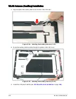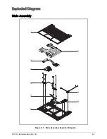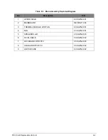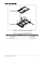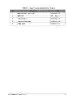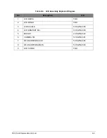
FRU (Field Replaceable Unit) List
6-13
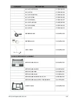
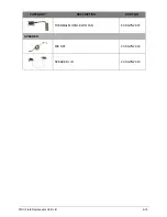
TOUCHPAD ASSY-BLACK
60.SGYN2.003
TOUCHPAD ASSY-SILVER
60.SGTN2.002
TOUCHPAD ASSY-RED
60.SGZN2.002
TOUCHPAD ASSY-BLUE
60.SH0N2.002
TOUCHPAD ASSY-SILVER FOR V5-171
60.M3AN2.002
UNILOAD DOOR
60.SGYN2.004
KB SUPPORT PLATE
33.SGYN2.001
HDD BRACKET
33.SGYN2.002
LCD BRACKET R&L
33.SGYN2.003
TBD
TBD
TBD
TBD
TBD
TBD
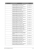
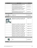
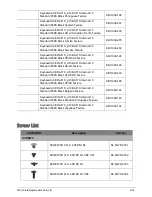
KEYBOARD
Keyboard ACER AF1S_A10B AF1S Internal 10
Standard 84KS Black US International Texture
KB.I100A.207
Keyboard ACER AF1S_A10B AF1S Internal 10
Standard 84KS Black Greek Texture
KB.I100A.191
Keyboard ACER AF1S_A10B AF1S Internal 10
Standard 84KS Black Arabic Texture
KB.I100A.181
Keyboard ACER AF1S_A10B AF1S Internal 10
Standard 84KS Black Chinese Texture
KB.I100A.186
Keyboard ACER AF1S_A10B AF1S Internal 10
Standard 84KS Black Russian Texture
KB.I100A.199
Keyboard ACER AF1S_A10B AF1S Internal 10
Standard 84KS Black US International w/ Hebrew
Texture
KB.I100A.208
CATEGORY
DESCRIPTION
PART NO.
Содержание AO756
Страница 1: ...AO756 V5 171 S E R V I C E G U I D E G U I D E ...
Страница 109: ...Service and Maintenance 5 14 Table 5 8 Base Door Screw Screw Name Screw Type Quantity M 2 0 x 6 0 1 ...
Страница 117: ...Service and Maintenance 5 22 4 Lift the fan by the fan cable to remove from its bay Figure 5 25 Removing the Fan ...
Страница 139: ...Service and Maintenance 5 44 4 Lift to remove the IO board from the lower case Figure 5 58 Removing the IO Board ...
Страница 147: ...Service and Maintenance 5 52 3 Lift to remove the left speaker Figure 5 70 Removing the Speakers 2 of 2 ...
Страница 151: ...Service and Maintenance 5 56 3 Lift to remove the keyboard Figure 5 76 Removing the Keyboard ...
Страница 160: ...5 65 Service and Maintenance Table 5 18 Thermal Module Screws Screw Name Screw Type Quantity M 2 0 x 3 0 4 ...
Страница 163: ...Service and Maintenance 5 68 5 Lift to remove the LCD module from the lower case Figure 5 94 Removing the LCD Module ...
Страница 170: ...5 75 Service and Maintenance 3 Lift to remove the LCD bezel Figure 5 104 Removing the LCD Bezel 3 of 3 ...
Страница 188: ...5 93 Service and Maintenance 3 Remove the main antenna from the LCD cover Figure 5 138 Removing the Main Antenna 3 of 3 ...
Страница 198: ...FRU Field Replaceable Unit List 6 6 Upper Case Assembly Figure 6 3 Upper Case Assembly Exploded Diagram 1 2 3 4 5 ...
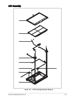
Страница 200: ...FRU Field Replaceable Unit List 6 8 LCD Assembly Figure 6 4 LCD Assembly Exploded Diagram 1 2 3 4 5 8 9 6 7 ...
Страница 212: ...CHAPTER 7 Test Compatible Components Test Compatible Components 7 2 Microsoft Windows 7 Environment Test 7 2 ...
Страница 217: ...CHAPTER 8 Online Support Information Online Support Information 8 2 Introduction 8 2 ...
Страница 219: ......


