1-17
Hardware Specifications and Configurations
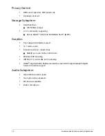
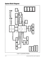
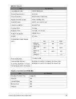
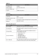
System Board Major Chips
Processor
NOTE:
Applicable product safety standards specify thermal limits for plastic surfaces. The computer
operates well within this range of temperatures.
Item
Specification
Core logic
Intel Panther Point-M PCH
VGA
Intel integrated
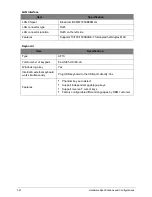
LAN
Broadcom BCM57785XB0KMLG QFN 68P E-LAN CTRL
USB 2.0
2 USB2.0 & 1 USB3.0
Super I/O controller
N/A
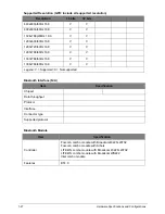
Bluetooth & Wireless
Foxconn T77H365.00(Broadcom 43228+20702)
Foxconn T77H348.02 WB222(Athors)
LITE-ON (Broadcom 43228+20702)
LITE-ON WCBN611AH-AA_WB222(Broadcom WB222)
Wireless
LITE-ON(Atheros HB125)
HON HAI(Broadcom 4313)
PCMCIA N/A
Audio codec
Realtek ALC271X-VB6-CG
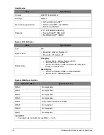
Item
Specification
CPU
Intel Sandy/Ivy Bridge Dual Core Processor
CPU package
BGA1023
Core logic
Intel Panther Point-M PCH
Chipset
Intel HM77/70 Express Chipset
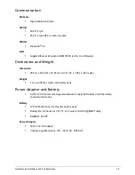
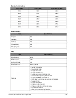
Item
Metric
Imperial
Содержание AO756
Страница 1: ...AO756 V5 171 S E R V I C E G U I D E G U I D E ...
Страница 109: ...Service and Maintenance 5 14 Table 5 8 Base Door Screw Screw Name Screw Type Quantity M 2 0 x 6 0 1 ...
Страница 117: ...Service and Maintenance 5 22 4 Lift the fan by the fan cable to remove from its bay Figure 5 25 Removing the Fan ...
Страница 139: ...Service and Maintenance 5 44 4 Lift to remove the IO board from the lower case Figure 5 58 Removing the IO Board ...
Страница 147: ...Service and Maintenance 5 52 3 Lift to remove the left speaker Figure 5 70 Removing the Speakers 2 of 2 ...
Страница 151: ...Service and Maintenance 5 56 3 Lift to remove the keyboard Figure 5 76 Removing the Keyboard ...
Страница 160: ...5 65 Service and Maintenance Table 5 18 Thermal Module Screws Screw Name Screw Type Quantity M 2 0 x 3 0 4 ...
Страница 163: ...Service and Maintenance 5 68 5 Lift to remove the LCD module from the lower case Figure 5 94 Removing the LCD Module ...
Страница 170: ...5 75 Service and Maintenance 3 Lift to remove the LCD bezel Figure 5 104 Removing the LCD Bezel 3 of 3 ...
Страница 188: ...5 93 Service and Maintenance 3 Remove the main antenna from the LCD cover Figure 5 138 Removing the Main Antenna 3 of 3 ...
Страница 198: ...FRU Field Replaceable Unit List 6 6 Upper Case Assembly Figure 6 3 Upper Case Assembly Exploded Diagram 1 2 3 4 5 ...
Страница 200: ...FRU Field Replaceable Unit List 6 8 LCD Assembly Figure 6 4 LCD Assembly Exploded Diagram 1 2 3 4 5 8 9 6 7 ...
Страница 212: ...CHAPTER 7 Test Compatible Components Test Compatible Components 7 2 Microsoft Windows 7 Environment Test 7 2 ...
Страница 217: ...CHAPTER 8 Online Support Information Online Support Information 8 2 Introduction 8 2 ...
Страница 219: ......

