2-21
System Utilities
HDD/BIOS Password
This section provides details about unlocking HDD password and removing the BIOS passwords.
Unlocking the HDD
NOTE:
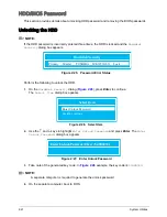
If the HDD password is incorrectly entered three times, the HDD is locked and the
Harddisk
Security
dialog box appears.
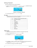
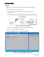
Figure 2:25. Password Error Status
Perform the following to unlock the HDD:
1.
On the
Harddisk Security
dialog (
Figure 2:26
), press Enter to continue.
The
Select Item
dialog box appears.
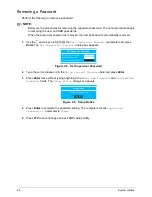
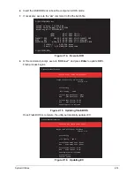
Figure 2:26. Select Item
2.
Use the
↑
and
↓
keys to highlight
Enter Unlock Password
and press Enter. The
Enter
Unlock Password
dialog box appears.
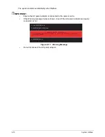
Figure 2:27. Enter Unlock Password
3.
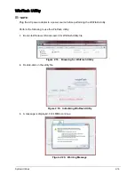
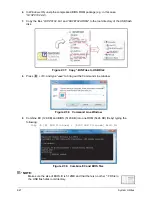
Take note of the generated key code. In
Figure 2:28
example, the key code is
54986933
.
NOTE:
A separate computer is required to generate the unlock password.
4.
On the separate computer, boot to DOS.
Harddisk Security
Primary Master
TOSHIBA MK3252GSX
Lock
Select Item
Enter Unlock Passowrd
System continue
Enter Unlock Password (Key: 54986933)
Содержание AO756
Страница 1: ...AO756 V5 171 S E R V I C E G U I D E G U I D E ...
Страница 109: ...Service and Maintenance 5 14 Table 5 8 Base Door Screw Screw Name Screw Type Quantity M 2 0 x 6 0 1 ...
Страница 117: ...Service and Maintenance 5 22 4 Lift the fan by the fan cable to remove from its bay Figure 5 25 Removing the Fan ...
Страница 139: ...Service and Maintenance 5 44 4 Lift to remove the IO board from the lower case Figure 5 58 Removing the IO Board ...
Страница 147: ...Service and Maintenance 5 52 3 Lift to remove the left speaker Figure 5 70 Removing the Speakers 2 of 2 ...
Страница 151: ...Service and Maintenance 5 56 3 Lift to remove the keyboard Figure 5 76 Removing the Keyboard ...
Страница 160: ...5 65 Service and Maintenance Table 5 18 Thermal Module Screws Screw Name Screw Type Quantity M 2 0 x 3 0 4 ...
Страница 163: ...Service and Maintenance 5 68 5 Lift to remove the LCD module from the lower case Figure 5 94 Removing the LCD Module ...
Страница 170: ...5 75 Service and Maintenance 3 Lift to remove the LCD bezel Figure 5 104 Removing the LCD Bezel 3 of 3 ...
Страница 188: ...5 93 Service and Maintenance 3 Remove the main antenna from the LCD cover Figure 5 138 Removing the Main Antenna 3 of 3 ...
Страница 198: ...FRU Field Replaceable Unit List 6 6 Upper Case Assembly Figure 6 3 Upper Case Assembly Exploded Diagram 1 2 3 4 5 ...
Страница 200: ...FRU Field Replaceable Unit List 6 8 LCD Assembly Figure 6 4 LCD Assembly Exploded Diagram 1 2 3 4 5 8 9 6 7 ...
Страница 212: ...CHAPTER 7 Test Compatible Components Test Compatible Components 7 2 Microsoft Windows 7 Environment Test 7 2 ...
Страница 217: ...CHAPTER 8 Online Support Information Online Support Information 8 2 Introduction 8 2 ...
Страница 219: ......

