
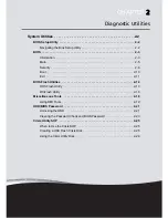


2-7
System Utilities
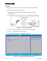
Setting a Password
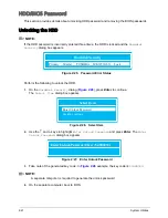
Perform the following to set the supervisor password:
1.
Use the
↑
and
↓
keys to highlight the
Set Supervisor Password
parameter and press
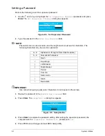
Enter. The
Set Supervisor Password
dialog box appears.
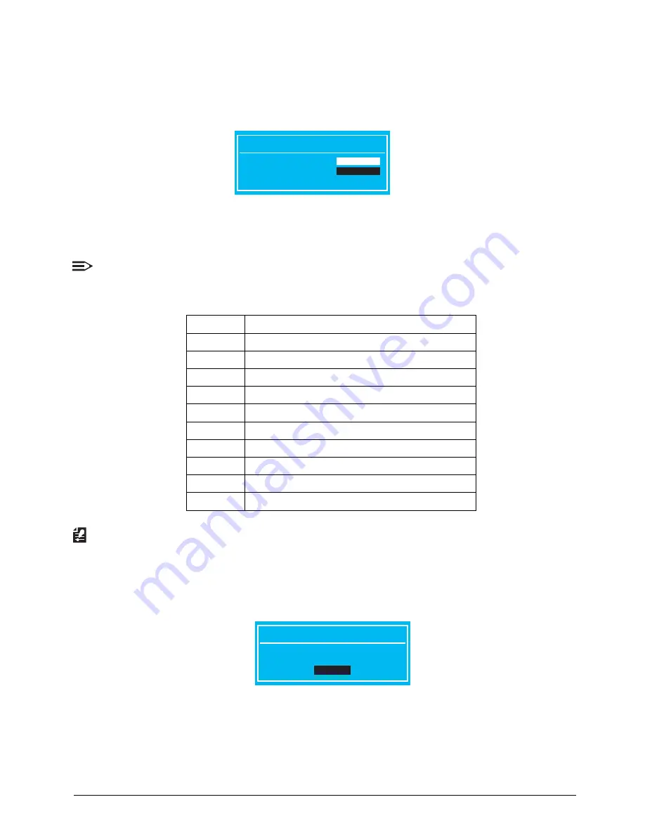
Figure 2:4. Set Supervisor Password
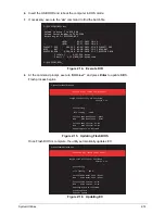
2.
Type the password in the
Enter New Password
field.
NOTE:
Passwords are not case sensitive and the length must not exceed 12 characters. The
following characters may be used in a password.
IMPORTANT:
Use care when typing a password. Characters do not appear on the screen.
3.
Retype the password in the
Confirm New Password
field.
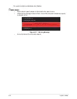
4.
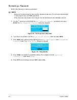
Press Enter. The
Setup Notice
dialog box appears.
Figure 2:5. Setup Notice
5.
Press Enter to complete the password setting. After setting the supervisor password, the
computer sets the
Supervisor Password Is
parameter to
Set
.
6.
Press F10 to save changes and exit BIOS Setup Utility.
A - Z
Alphabets A through Z (Not Case Sensitive)
0 - 9
Numerical Characters
-
Dash
=
Equal Sign
[
Left Bracket
]
Right Bracket
.
Period
,
Comma
;
Semi-colon
/
Slash
\
Back-slash
Set Supervisor Password
Enter New Password
[
]
Confirm New Password
[
]
Setup Notice
Changes have been saved.
[Continue]
Содержание AO756
Страница 1: ...AO756 V5 171 S E R V I C E G U I D E G U I D E ...
Страница 109: ...Service and Maintenance 5 14 Table 5 8 Base Door Screw Screw Name Screw Type Quantity M 2 0 x 6 0 1 ...
Страница 117: ...Service and Maintenance 5 22 4 Lift the fan by the fan cable to remove from its bay Figure 5 25 Removing the Fan ...
Страница 139: ...Service and Maintenance 5 44 4 Lift to remove the IO board from the lower case Figure 5 58 Removing the IO Board ...
Страница 147: ...Service and Maintenance 5 52 3 Lift to remove the left speaker Figure 5 70 Removing the Speakers 2 of 2 ...
Страница 151: ...Service and Maintenance 5 56 3 Lift to remove the keyboard Figure 5 76 Removing the Keyboard ...
Страница 160: ...5 65 Service and Maintenance Table 5 18 Thermal Module Screws Screw Name Screw Type Quantity M 2 0 x 3 0 4 ...
Страница 163: ...Service and Maintenance 5 68 5 Lift to remove the LCD module from the lower case Figure 5 94 Removing the LCD Module ...
Страница 170: ...5 75 Service and Maintenance 3 Lift to remove the LCD bezel Figure 5 104 Removing the LCD Bezel 3 of 3 ...
Страница 188: ...5 93 Service and Maintenance 3 Remove the main antenna from the LCD cover Figure 5 138 Removing the Main Antenna 3 of 3 ...
Страница 198: ...FRU Field Replaceable Unit List 6 6 Upper Case Assembly Figure 6 3 Upper Case Assembly Exploded Diagram 1 2 3 4 5 ...
Страница 200: ...FRU Field Replaceable Unit List 6 8 LCD Assembly Figure 6 4 LCD Assembly Exploded Diagram 1 2 3 4 5 8 9 6 7 ...
Страница 212: ...CHAPTER 7 Test Compatible Components Test Compatible Components 7 2 Microsoft Windows 7 Environment Test 7 2 ...
Страница 217: ...CHAPTER 8 Online Support Information Online Support Information 8 2 Introduction 8 2 ...
Страница 219: ......