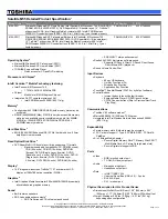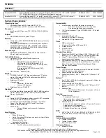
Hardware Specifications and Configurations
1-18
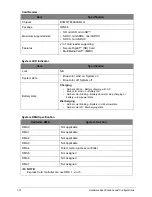
Processor Specifications
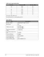
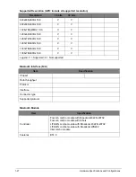
CPU Fan True Value Table (Tj=105)
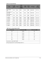
Item
CPU
Speed
Cores
Bus
Speed
(FSB/
DMI/QBI)
Mfg
Tech
Cache
Size
Package
Core
Voltage
Intel Celeron
877
1.4G
dual
5GT/s
32nm
2MB
BGA1023
0.7-1.2V
Pentium Dual
Core 987
1.5G
dual
5GT/s
32nm
2MB
BGA1023
0.7-1.2V
Pentium Dual
Core 967
1.3G
dual
5GT/s
32nm
2MB
BGA1023
0.7-1.2V
i5-2467M
1.6G
dual
5GT/s
32nm
3MB
BGA1023
0.7-1.2V
i3-2367M
1.4G
dual
5GT/s
32nm
3MB
BGA1023
0.7-1.2V
i3-2377M
1.5G
dual
5GT/s
32nm
3M
BGA1023
0.7-1.2V
i5-3317U
1.7G
dual
5GT/s
22nm
3M
BGA1023
0.7-1.2V
i3-3217U
1.8G
dual
5GT/s
22nm
3M
BGA1023
0.7-1.2V
i7-3667U
2.0G
dual
5GT/s
22nm
3M
BGA1023
0.7-1.2V
CPU Temp
Fan Speed (RPM)
SPL Spec (dBA)
50
3400
25
57
3700
28
64
4100
31
71
4700
34
78
5200
37
85
5400
40
Pro-hot: On= 104°C; OFF= 96°C
OS shut down at 105 °C; H/W shut down at 92 °C
Содержание AO756
Страница 1: ...AO756 V5 171 S E R V I C E G U I D E G U I D E ...
Страница 109: ...Service and Maintenance 5 14 Table 5 8 Base Door Screw Screw Name Screw Type Quantity M 2 0 x 6 0 1 ...
Страница 117: ...Service and Maintenance 5 22 4 Lift the fan by the fan cable to remove from its bay Figure 5 25 Removing the Fan ...
Страница 139: ...Service and Maintenance 5 44 4 Lift to remove the IO board from the lower case Figure 5 58 Removing the IO Board ...
Страница 147: ...Service and Maintenance 5 52 3 Lift to remove the left speaker Figure 5 70 Removing the Speakers 2 of 2 ...
Страница 151: ...Service and Maintenance 5 56 3 Lift to remove the keyboard Figure 5 76 Removing the Keyboard ...
Страница 160: ...5 65 Service and Maintenance Table 5 18 Thermal Module Screws Screw Name Screw Type Quantity M 2 0 x 3 0 4 ...
Страница 163: ...Service and Maintenance 5 68 5 Lift to remove the LCD module from the lower case Figure 5 94 Removing the LCD Module ...
Страница 170: ...5 75 Service and Maintenance 3 Lift to remove the LCD bezel Figure 5 104 Removing the LCD Bezel 3 of 3 ...
Страница 188: ...5 93 Service and Maintenance 3 Remove the main antenna from the LCD cover Figure 5 138 Removing the Main Antenna 3 of 3 ...
Страница 198: ...FRU Field Replaceable Unit List 6 6 Upper Case Assembly Figure 6 3 Upper Case Assembly Exploded Diagram 1 2 3 4 5 ...
Страница 200: ...FRU Field Replaceable Unit List 6 8 LCD Assembly Figure 6 4 LCD Assembly Exploded Diagram 1 2 3 4 5 8 9 6 7 ...
Страница 212: ...CHAPTER 7 Test Compatible Components Test Compatible Components 7 2 Microsoft Windows 7 Environment Test 7 2 ...
Страница 217: ...CHAPTER 8 Online Support Information Online Support Information 8 2 Introduction 8 2 ...
Страница 219: ......

