1-33
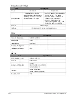
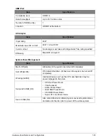
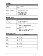
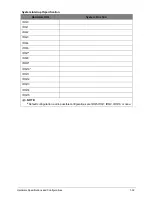
Hardware Specifications and Configurations
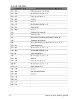
System IO Address Map
I/O Address (hex)
System Function (Shipping Configuration)
000 - 00F
DMA controller no. 1 & PCI bus
010 - 01F
Motherboard resources no. 1
020 - 021
Interrupt controller no. 1
022 - 024
Unused
025 - 03F
Unused
02E - 02F
Motherboard resources no. 2
040 - 05F
System timer
044 - 05F
Unused
060 Standard
PS/2
Keyboard
061 System
speaker
062
Microsoft ACPI-Compliant Embedded Controller no. 1
064 Standard
PS/2
Keyboard
066
Microsoft ACPI-Compliant Embedded Controller no. 2
070 - 071
System CMOS/RTC
072 - 073
Motherboard resources no. 3
080 - 080
Motherboard resources no. 4
081-08F
DMA controller no. 2
092
Motherboard resources no. 5
093 - 09F
Unused
0A0 - 0A1
Interrupt controller no. 2
0B0 0B
Motherboard resources no. 6
0C0 - 0DF
DMA controller no. 3
0E0 - 0EF
Unused
0F0 - 0FE
Numeric data processor
0F2 - 3AF
Unused
3B0 - 3BB
3BC - 3BF
3C0 - 3DF
3E0 - 3E1
Содержание AO756
Страница 1: ...AO756 V5 171 S E R V I C E G U I D E G U I D E ...
Страница 109: ...Service and Maintenance 5 14 Table 5 8 Base Door Screw Screw Name Screw Type Quantity M 2 0 x 6 0 1 ...
Страница 117: ...Service and Maintenance 5 22 4 Lift the fan by the fan cable to remove from its bay Figure 5 25 Removing the Fan ...
Страница 139: ...Service and Maintenance 5 44 4 Lift to remove the IO board from the lower case Figure 5 58 Removing the IO Board ...
Страница 147: ...Service and Maintenance 5 52 3 Lift to remove the left speaker Figure 5 70 Removing the Speakers 2 of 2 ...
Страница 151: ...Service and Maintenance 5 56 3 Lift to remove the keyboard Figure 5 76 Removing the Keyboard ...
Страница 160: ...5 65 Service and Maintenance Table 5 18 Thermal Module Screws Screw Name Screw Type Quantity M 2 0 x 3 0 4 ...
Страница 163: ...Service and Maintenance 5 68 5 Lift to remove the LCD module from the lower case Figure 5 94 Removing the LCD Module ...
Страница 170: ...5 75 Service and Maintenance 3 Lift to remove the LCD bezel Figure 5 104 Removing the LCD Bezel 3 of 3 ...
Страница 188: ...5 93 Service and Maintenance 3 Remove the main antenna from the LCD cover Figure 5 138 Removing the Main Antenna 3 of 3 ...
Страница 198: ...FRU Field Replaceable Unit List 6 6 Upper Case Assembly Figure 6 3 Upper Case Assembly Exploded Diagram 1 2 3 4 5 ...
Страница 200: ...FRU Field Replaceable Unit List 6 8 LCD Assembly Figure 6 4 LCD Assembly Exploded Diagram 1 2 3 4 5 8 9 6 7 ...
Страница 212: ...CHAPTER 7 Test Compatible Components Test Compatible Components 7 2 Microsoft Windows 7 Environment Test 7 2 ...
Страница 217: ...CHAPTER 8 Online Support Information Online Support Information 8 2 Introduction 8 2 ...
Страница 219: ......

