1-25
Hardware Specifications and Configurations
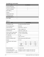
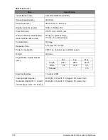
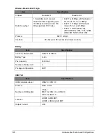
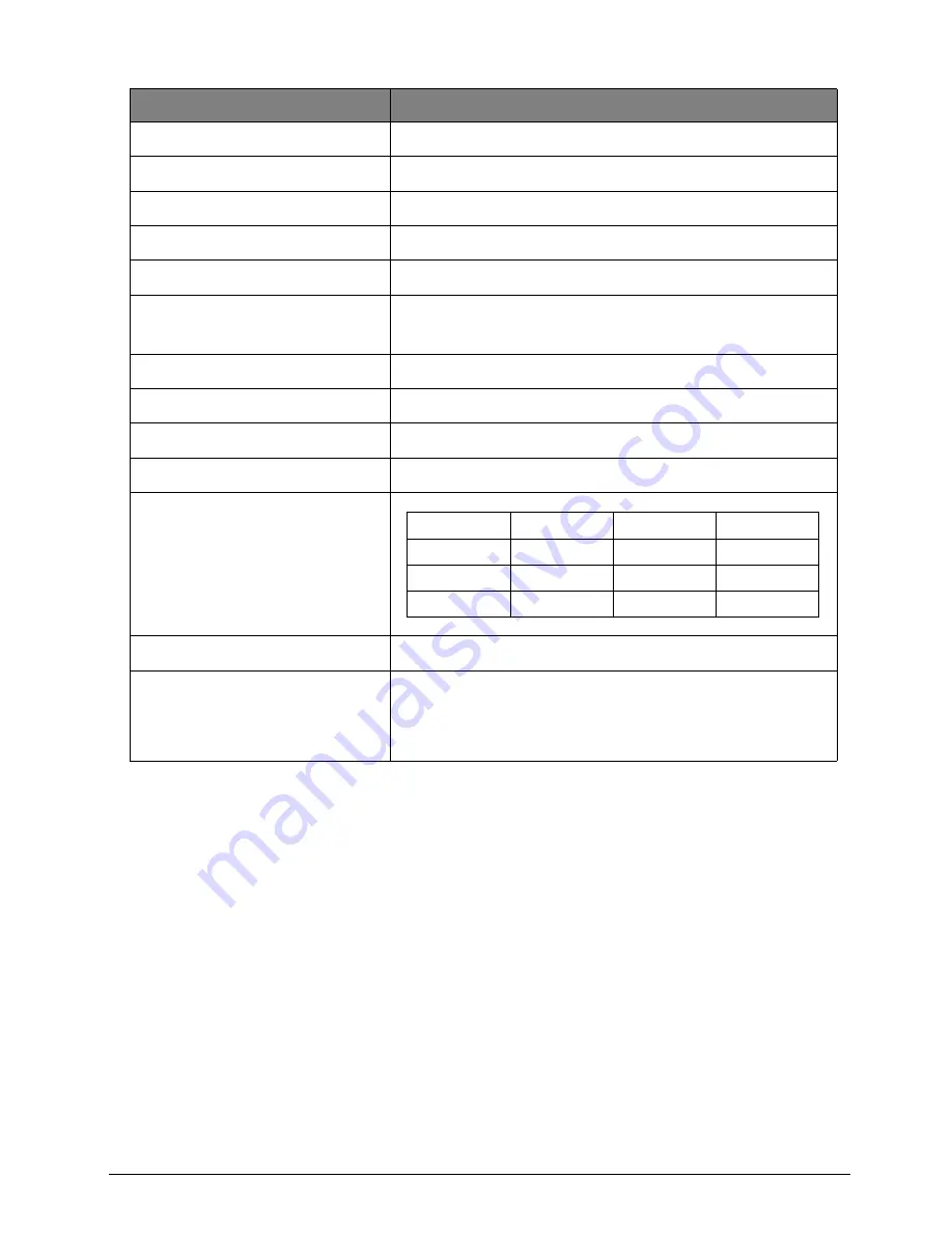
LED 11.6 (Con’t.)
Item
Specification
Vendor/Model name
AUO B116XW03 V2 (H/W:1B)
Screen Diagonal (mm)
293.8 mm
Active Area (mm)
256.125 mm x 144.0 mm
Display resolution (pixels)
1366 x 3(RGB) x 768
Pixel Pitch (mm)
0.1875 mm × 0.1875 mm
White Luminance (ILED=20mA)
(Note: ILED is LED current)
200 typ. (5 points average_
170 min. (5 points average)
Contrast Ratio
500 type
Response Time
8 ms type / 16 ms max
Power Consumption
2.9W max. (include Logic and BLU power)
Weight
235 max
Physical Size include bracket
(mm)
Electrical Interface
1 channel LVDS
Viewing Angle (degree)
Horizontal (Right) CR = 10 (Left)
Vertical (Upper) CR = 10 (Lower)
40 (Right) / 40 (Left) / 10 (Upper) / 30 (Lower) min.
45 (Right) / 45 (Left) / 15 (Upper) / 35 (Lower) typ.
Min.
Typ.
Max.
Length
267.5
268.0
268.5
Width
174
174.5
175
Thickness
-
-
3.6
Содержание AO756
Страница 1: ...AO756 V5 171 S E R V I C E G U I D E G U I D E ...
Страница 109: ...Service and Maintenance 5 14 Table 5 8 Base Door Screw Screw Name Screw Type Quantity M 2 0 x 6 0 1 ...
Страница 117: ...Service and Maintenance 5 22 4 Lift the fan by the fan cable to remove from its bay Figure 5 25 Removing the Fan ...
Страница 139: ...Service and Maintenance 5 44 4 Lift to remove the IO board from the lower case Figure 5 58 Removing the IO Board ...
Страница 147: ...Service and Maintenance 5 52 3 Lift to remove the left speaker Figure 5 70 Removing the Speakers 2 of 2 ...
Страница 151: ...Service and Maintenance 5 56 3 Lift to remove the keyboard Figure 5 76 Removing the Keyboard ...
Страница 160: ...5 65 Service and Maintenance Table 5 18 Thermal Module Screws Screw Name Screw Type Quantity M 2 0 x 3 0 4 ...
Страница 163: ...Service and Maintenance 5 68 5 Lift to remove the LCD module from the lower case Figure 5 94 Removing the LCD Module ...
Страница 170: ...5 75 Service and Maintenance 3 Lift to remove the LCD bezel Figure 5 104 Removing the LCD Bezel 3 of 3 ...
Страница 188: ...5 93 Service and Maintenance 3 Remove the main antenna from the LCD cover Figure 5 138 Removing the Main Antenna 3 of 3 ...
Страница 198: ...FRU Field Replaceable Unit List 6 6 Upper Case Assembly Figure 6 3 Upper Case Assembly Exploded Diagram 1 2 3 4 5 ...
Страница 200: ...FRU Field Replaceable Unit List 6 8 LCD Assembly Figure 6 4 LCD Assembly Exploded Diagram 1 2 3 4 5 8 9 6 7 ...
Страница 212: ...CHAPTER 7 Test Compatible Components Test Compatible Components 7 2 Microsoft Windows 7 Environment Test 7 2 ...
Страница 217: ...CHAPTER 8 Online Support Information Online Support Information 8 2 Introduction 8 2 ...
Страница 219: ......


