Troubleshooting
4-4
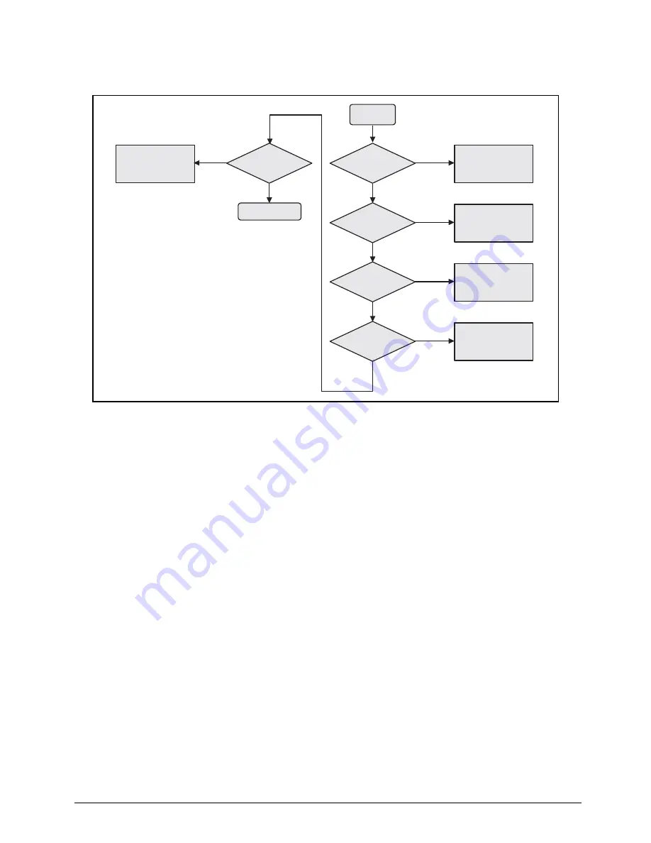
No Display Issues
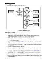
If the system does not display, perform the following:
Figure 4:2. No Display Issues
No POST or Video
If the POST or video does not appear, perform the following:
1.
Make sure that internal display is selected. Switching between internal and external by
pressing Fn+F5. Reference Product pages for specific model procedures.
2.
Make sure the computer has power by checking for one of the following:
•
Fans start up
•
Status LEDs illuminate
3.
If there is no power, refer to
Power On Issues
on page
4-3
. Otherwise, continue to the next
step.
4.
If there is power, drain the stored power by removing the power cable. Hold the power button
for 10 seconds.
5.
Connect the power and reboot the computer.
6.
Connect an external monitor to the computer and switch between the internal display and the
external display is by pressing Fn+F5.
7.
If the POST or video appears on the external display only, refer to
LCD Picture Failure
on
page
4-6
. Otherwise, continue to the next step.
8.
Disconnect the power and all external devices including port replicators or docking stations.
9.
Remove any memory cards and CD/DVD discs.
10.
Start the computer. If the computer boots correctly, add the devices one by one until the failure
point is discovered.
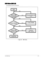
Start
Can
Power on
RAM
module well
connected
Go to no power
Trouble shooting
step
NG
Replace LCD
panel/cable
NG
Connect it well
OK
OK
OK
LCD
panel/cable
ok
OK
NG
RAM
module OK
Replace RAM
module
NG
OK
Lcd cable
well
connected
Connect it well
NG
Replace M/B
Содержание AO756
Страница 1: ...AO756 V5 171 S E R V I C E G U I D E G U I D E ...
Страница 109: ...Service and Maintenance 5 14 Table 5 8 Base Door Screw Screw Name Screw Type Quantity M 2 0 x 6 0 1 ...
Страница 117: ...Service and Maintenance 5 22 4 Lift the fan by the fan cable to remove from its bay Figure 5 25 Removing the Fan ...
Страница 139: ...Service and Maintenance 5 44 4 Lift to remove the IO board from the lower case Figure 5 58 Removing the IO Board ...
Страница 147: ...Service and Maintenance 5 52 3 Lift to remove the left speaker Figure 5 70 Removing the Speakers 2 of 2 ...
Страница 151: ...Service and Maintenance 5 56 3 Lift to remove the keyboard Figure 5 76 Removing the Keyboard ...
Страница 160: ...5 65 Service and Maintenance Table 5 18 Thermal Module Screws Screw Name Screw Type Quantity M 2 0 x 3 0 4 ...
Страница 163: ...Service and Maintenance 5 68 5 Lift to remove the LCD module from the lower case Figure 5 94 Removing the LCD Module ...
Страница 170: ...5 75 Service and Maintenance 3 Lift to remove the LCD bezel Figure 5 104 Removing the LCD Bezel 3 of 3 ...
Страница 188: ...5 93 Service and Maintenance 3 Remove the main antenna from the LCD cover Figure 5 138 Removing the Main Antenna 3 of 3 ...
Страница 198: ...FRU Field Replaceable Unit List 6 6 Upper Case Assembly Figure 6 3 Upper Case Assembly Exploded Diagram 1 2 3 4 5 ...
Страница 200: ...FRU Field Replaceable Unit List 6 8 LCD Assembly Figure 6 4 LCD Assembly Exploded Diagram 1 2 3 4 5 8 9 6 7 ...
Страница 212: ...CHAPTER 7 Test Compatible Components Test Compatible Components 7 2 Microsoft Windows 7 Environment Test 7 2 ...
Страница 217: ...CHAPTER 8 Online Support Information Online Support Information 8 2 Introduction 8 2 ...
Страница 219: ......

