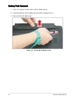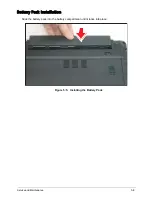
4-11
Troubleshooting
Internal Microphone Failure
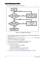
If the internal microphone fails, perform the following:
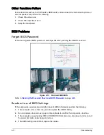
Figure 4:7. Internal Microphone Failure
1.
Check that the microphone is enabled. Navigate to Start > Control Panel > Hardware and
Sound > Sound and select the
Recording
tab.
2.
Right click on the
Recording
tab and select
Show Disabled Devices
(clear by default).
The microphone appears on the
Recording
tab.
3.
Right click on the microphone and select Enable.
4.
Select the microphone then click Properties. Select the Levels tab.
5.
Increase the volume to the maximum setting and click OK.
6.
Test the microphone hardware:
•
Select the microphone and click Configure.
•
Select Set up microphone.
•
Select the microphone type from the list and click Next.
•
Follow the on-screen prompts to complete the test.
7.
If the issue is still not resolved, refer to
Online Support Information
on page
8-2
.
Start
Swap M/B
Check M/B
MIC cable
Check MIC
module where
OK
Re-assemble the
MIC cable to M/B
OK
NG
Swap MIC
module
OK
OK
NG
Содержание AO756
Страница 1: ...AO756 V5 171 S E R V I C E G U I D E G U I D E ...
Страница 109: ...Service and Maintenance 5 14 Table 5 8 Base Door Screw Screw Name Screw Type Quantity M 2 0 x 6 0 1 ...
Страница 117: ...Service and Maintenance 5 22 4 Lift the fan by the fan cable to remove from its bay Figure 5 25 Removing the Fan ...
Страница 139: ...Service and Maintenance 5 44 4 Lift to remove the IO board from the lower case Figure 5 58 Removing the IO Board ...
Страница 147: ...Service and Maintenance 5 52 3 Lift to remove the left speaker Figure 5 70 Removing the Speakers 2 of 2 ...
Страница 151: ...Service and Maintenance 5 56 3 Lift to remove the keyboard Figure 5 76 Removing the Keyboard ...
Страница 160: ...5 65 Service and Maintenance Table 5 18 Thermal Module Screws Screw Name Screw Type Quantity M 2 0 x 3 0 4 ...
Страница 163: ...Service and Maintenance 5 68 5 Lift to remove the LCD module from the lower case Figure 5 94 Removing the LCD Module ...
Страница 170: ...5 75 Service and Maintenance 3 Lift to remove the LCD bezel Figure 5 104 Removing the LCD Bezel 3 of 3 ...
Страница 188: ...5 93 Service and Maintenance 3 Remove the main antenna from the LCD cover Figure 5 138 Removing the Main Antenna 3 of 3 ...
Страница 198: ...FRU Field Replaceable Unit List 6 6 Upper Case Assembly Figure 6 3 Upper Case Assembly Exploded Diagram 1 2 3 4 5 ...
Страница 200: ...FRU Field Replaceable Unit List 6 8 LCD Assembly Figure 6 4 LCD Assembly Exploded Diagram 1 2 3 4 5 8 9 6 7 ...
Страница 212: ...CHAPTER 7 Test Compatible Components Test Compatible Components 7 2 Microsoft Windows 7 Environment Test 7 2 ...
Страница 217: ...CHAPTER 8 Online Support Information Online Support Information 8 2 Introduction 8 2 ...
Страница 219: ......

