2-5
System Utilities
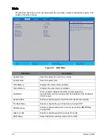
Main
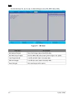
The Main tab allows the user to set the system time and date, enable or disable boot option, and
enable or disable recovery.
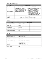
Figure 2:2. BIOS Main
Parameter
Description
System Time
Sets the system time in 24-hour format.
System Date
Sets the system date.
Total Memory
Displays the total memory installed.
Video Memory
Displays the video memory installed.
Quiet Boot
When enabled, displays the OEM (original equipment
manufacturer) screen during system boot instead of the traditional
POST screen.
Network Boot
Enable or disable system boot from LAN (local area network).
F12 Boot Menu
Enable or disable the use of boot menu during POST.
D2D Recovery
Enable or disable disc-to-disc recovery by pressing Alt+F10 key
during POST.
Wake on LAN
Enable or disable system to wake up from LAN.
SATA Mode
Select the SATA controller mode: AHCI or IDE.
F9
Setup Defaults
F10
Save and Exit
F1
Esc
Help
Exit
Select Item
Select Menu
Enter
F5/F6
Select Sub-Menu
Change Values
InsydeH20 Setup Utility
Rev. 3.7
Main
System Time :
[19
:03:49]
System Date :
[01/01/2012]
Total Memory:
2048 MB
Video Memory:
128MB
Quiet Boot
[Enable]
Network Boot
[Enable]
F12 Boot Menu
[Disable]
D2D Recovery
[Enable]
Wake on LAN
[Disable]
SATA Mode
[AHCI Mode]
Information
Security
Exit
Boot
T h i s i s t h e h e l p o f t h e
[ H o u r : M i n u t e : S e c o n d ] f i e l d . H o u r v a l i d
r a n g e i s f r o m 0 t o 2 3 , M i n u t e i s f r o m 0
t o 5 9 , S e c o n d i s f r o m 0 t o 5 9 . INCREASE/
R E D U C E : F 6 / F 5 .
I t e m S p e c i f i c H e l p
Содержание AO756
Страница 1: ...AO756 V5 171 S E R V I C E G U I D E G U I D E ...
Страница 109: ...Service and Maintenance 5 14 Table 5 8 Base Door Screw Screw Name Screw Type Quantity M 2 0 x 6 0 1 ...
Страница 117: ...Service and Maintenance 5 22 4 Lift the fan by the fan cable to remove from its bay Figure 5 25 Removing the Fan ...
Страница 139: ...Service and Maintenance 5 44 4 Lift to remove the IO board from the lower case Figure 5 58 Removing the IO Board ...
Страница 147: ...Service and Maintenance 5 52 3 Lift to remove the left speaker Figure 5 70 Removing the Speakers 2 of 2 ...
Страница 151: ...Service and Maintenance 5 56 3 Lift to remove the keyboard Figure 5 76 Removing the Keyboard ...
Страница 160: ...5 65 Service and Maintenance Table 5 18 Thermal Module Screws Screw Name Screw Type Quantity M 2 0 x 3 0 4 ...
Страница 163: ...Service and Maintenance 5 68 5 Lift to remove the LCD module from the lower case Figure 5 94 Removing the LCD Module ...
Страница 170: ...5 75 Service and Maintenance 3 Lift to remove the LCD bezel Figure 5 104 Removing the LCD Bezel 3 of 3 ...
Страница 188: ...5 93 Service and Maintenance 3 Remove the main antenna from the LCD cover Figure 5 138 Removing the Main Antenna 3 of 3 ...
Страница 198: ...FRU Field Replaceable Unit List 6 6 Upper Case Assembly Figure 6 3 Upper Case Assembly Exploded Diagram 1 2 3 4 5 ...
Страница 200: ...FRU Field Replaceable Unit List 6 8 LCD Assembly Figure 6 4 LCD Assembly Exploded Diagram 1 2 3 4 5 8 9 6 7 ...
Страница 212: ...CHAPTER 7 Test Compatible Components Test Compatible Components 7 2 Microsoft Windows 7 Environment Test 7 2 ...
Страница 217: ...CHAPTER 8 Online Support Information Online Support Information 8 2 Introduction 8 2 ...
Страница 219: ......

