1-15
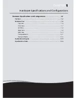
Hardware Specifications and Configurations
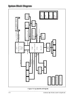
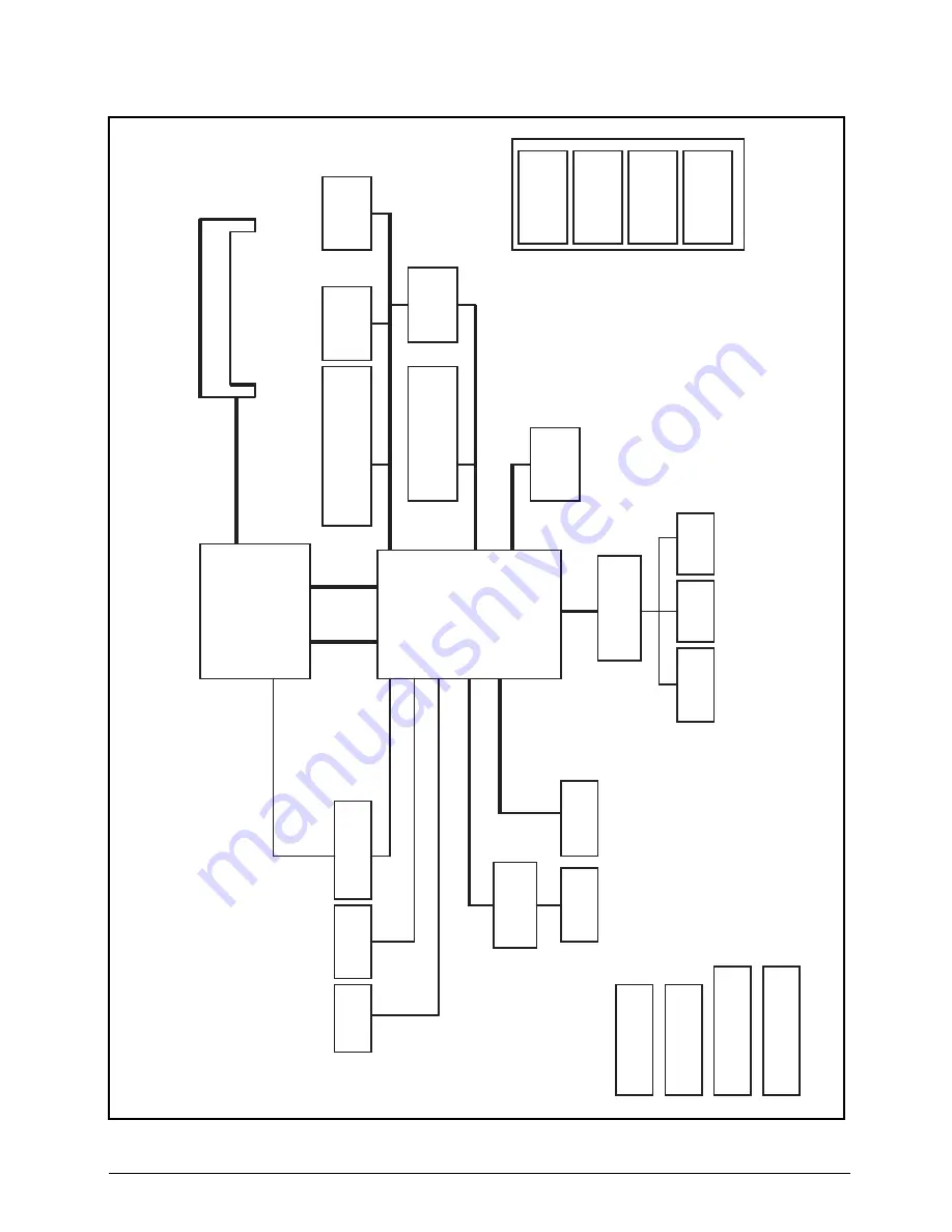
System Block Diagram
Figure 1:8. System Block Diagram
LVDS/e
DP Conn.
HDMI Conn.
L
V
DS(UMA)
T
M
DS(UMA)
CLK=
100M
Hz
CLK=
3
3M
Hz
2.5GB/s x4
DM
I x4
100M
Hz
FDI x8
SPI
S
A
T
A
x 6 (
G
EN
2 3.0G
T
/S
,G
EN
3 6G
T
/S
)
RT
C CKT
.
3.3V 24M
Hz
CM
OS
Camera
P
C
I-
Expr
es
s x 8
(P
CIE2.0 5G
T/s)
Dual
C
hannel
2.7GT/s
Powe
r On/Off CKT.
Touc
h Pad
LP
C B
U
S
Proce
ssor
BANK 0
, 1
, 2
, 3
USB 2.0
conn x
1
(Option for USB3.0)
DC/DC I
n
te
rfac
e CKT.
Sandy
Bri
dge
ULV
Powe
r Circ
uit DC/DC
204pin DDRIII-SO-DIMM X2
Int
el
1.5V DDRIII 1066/1333
Mem
o
ry B
U
S(
D
D
R
III)
PCH
HD A
u
di
o
Panther Point-M
E
N
E
KB9012
BGA1023
Inte
l
SPI ROM x
2
U
S
Bx14
3.3V
48MH
z
SATA HDD
Conn.
989pin BGA
LAN(
GbE)
/CardRe
ade
r
Br
oadc
om
57785
CLK=
100M
Hz
eDP(UMA)
IO/
B
USB 2.
0
conn x
2
GE
N3
LS-8942P
Port 1
100M
H
z
MIN
I C
a
rd
WL
A
N
Port 8
Port 2,3
Port 10
2
t
r
o
P
3
t
r
o
P
ALC271X-VB6
HDA Code
c
Int. Spe
ake
r
Port 0
17W
LED/
B
LS-8941P
LS-8943P
HDD/
B
CRT Conn
RGB(UMA)
In
t.KBD
T
PM
TPM
/B
LS-8944P
Содержание AO756
Страница 1: ...AO756 V5 171 S E R V I C E G U I D E G U I D E ...
Страница 109: ...Service and Maintenance 5 14 Table 5 8 Base Door Screw Screw Name Screw Type Quantity M 2 0 x 6 0 1 ...
Страница 117: ...Service and Maintenance 5 22 4 Lift the fan by the fan cable to remove from its bay Figure 5 25 Removing the Fan ...
Страница 139: ...Service and Maintenance 5 44 4 Lift to remove the IO board from the lower case Figure 5 58 Removing the IO Board ...
Страница 147: ...Service and Maintenance 5 52 3 Lift to remove the left speaker Figure 5 70 Removing the Speakers 2 of 2 ...
Страница 151: ...Service and Maintenance 5 56 3 Lift to remove the keyboard Figure 5 76 Removing the Keyboard ...
Страница 160: ...5 65 Service and Maintenance Table 5 18 Thermal Module Screws Screw Name Screw Type Quantity M 2 0 x 3 0 4 ...
Страница 163: ...Service and Maintenance 5 68 5 Lift to remove the LCD module from the lower case Figure 5 94 Removing the LCD Module ...
Страница 170: ...5 75 Service and Maintenance 3 Lift to remove the LCD bezel Figure 5 104 Removing the LCD Bezel 3 of 3 ...
Страница 188: ...5 93 Service and Maintenance 3 Remove the main antenna from the LCD cover Figure 5 138 Removing the Main Antenna 3 of 3 ...
Страница 198: ...FRU Field Replaceable Unit List 6 6 Upper Case Assembly Figure 6 3 Upper Case Assembly Exploded Diagram 1 2 3 4 5 ...
Страница 200: ...FRU Field Replaceable Unit List 6 8 LCD Assembly Figure 6 4 LCD Assembly Exploded Diagram 1 2 3 4 5 8 9 6 7 ...
Страница 212: ...CHAPTER 7 Test Compatible Components Test Compatible Components 7 2 Microsoft Windows 7 Environment Test 7 2 ...
Страница 217: ...CHAPTER 8 Online Support Information Online Support Information 8 2 Introduction 8 2 ...
Страница 219: ......

