System Utilities
2-14
6.
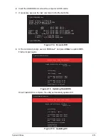
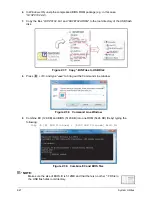
Insert the USB HDD and reboot the computer in DOS mode.
7.
If necessary, execute the “
dir
” command to find the batch file.
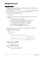
Figure 2:14. Execute DIR
8.
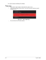
At the command prompt, execute “
BIOS.bat”
and press Enter to update BIOS.
Flash process begins.
Figure 2:15. Updating Flash BIOS
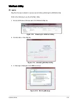
Once Flash BIOS is complete, the utility automatically updates EC.
Figure 2:16. Updating EC
C:\Q1VZC102\DOS>dir
Volume in drive C is USB_8GB
Volume Serial Number is 3666-33A4
Directory of C:\Q1VZC102\DOS
.
..
FLASHIT
EXE
<DIR>
<DIR>
102,912
03-27-2012
03-27-2012
07-19-2011
18:46 .
18:46 ..
17:49 FLASHIT.EXE
BIOS
BAT
Q1VZC102 BIN
338
4,194,304
03-30-2011
03-30-2010
13:15 BIOS.BAT
17:37 Q1VZC102.BIN
3 file(s)
2
_
dir(s)
4,297,554
_
bytes
2,524,848,128
_
bytes
_
free
C:\Q1VZC102\DOS>_
C:\Q1VZC102\DOS>BIOS.bat
Please do not remove the AC power!
Insyde
_
Flash
_
Utility
_
for
_
InsydeH2O
_
Version 1.5o
Initializing
File
_
loading
100
_
%
Current BIOS Model name : Q1VZC
New
BIOS Model name : Q1VZC
Current BIOS version: V1.01
New
BIOS version: V1.02
_
Updating Block at FFFFF000
C:\Q1VZC102\DOS>BIOS.bat
Please do not remove the AC power!
Insyde
_
Flash
_
Utility
_
for
_
InsydeH2O
_
Version 1.5o
Initializing
File
_
loading
100
_
%
Current BIOS Model name : Q1VZC
New
BIOS Model name : Q1VZC
Current BIOS version: V1.01
New
BIOS version: V1.02
_
Updating
Flash Complete!
Start EC update
Block at FFFFF000
Содержание AO756
Страница 1: ...AO756 V5 171 S E R V I C E G U I D E G U I D E ...
Страница 109: ...Service and Maintenance 5 14 Table 5 8 Base Door Screw Screw Name Screw Type Quantity M 2 0 x 6 0 1 ...
Страница 117: ...Service and Maintenance 5 22 4 Lift the fan by the fan cable to remove from its bay Figure 5 25 Removing the Fan ...
Страница 139: ...Service and Maintenance 5 44 4 Lift to remove the IO board from the lower case Figure 5 58 Removing the IO Board ...
Страница 147: ...Service and Maintenance 5 52 3 Lift to remove the left speaker Figure 5 70 Removing the Speakers 2 of 2 ...
Страница 151: ...Service and Maintenance 5 56 3 Lift to remove the keyboard Figure 5 76 Removing the Keyboard ...
Страница 160: ...5 65 Service and Maintenance Table 5 18 Thermal Module Screws Screw Name Screw Type Quantity M 2 0 x 3 0 4 ...
Страница 163: ...Service and Maintenance 5 68 5 Lift to remove the LCD module from the lower case Figure 5 94 Removing the LCD Module ...
Страница 170: ...5 75 Service and Maintenance 3 Lift to remove the LCD bezel Figure 5 104 Removing the LCD Bezel 3 of 3 ...
Страница 188: ...5 93 Service and Maintenance 3 Remove the main antenna from the LCD cover Figure 5 138 Removing the Main Antenna 3 of 3 ...
Страница 198: ...FRU Field Replaceable Unit List 6 6 Upper Case Assembly Figure 6 3 Upper Case Assembly Exploded Diagram 1 2 3 4 5 ...
Страница 200: ...FRU Field Replaceable Unit List 6 8 LCD Assembly Figure 6 4 LCD Assembly Exploded Diagram 1 2 3 4 5 8 9 6 7 ...
Страница 212: ...CHAPTER 7 Test Compatible Components Test Compatible Components 7 2 Microsoft Windows 7 Environment Test 7 2 ...
Страница 217: ...CHAPTER 8 Online Support Information Online Support Information 8 2 Introduction 8 2 ...
Страница 219: ......


