30 Electrical installation
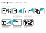
Connecting the module to the DeviceNet network
Connect the bus cable to terminal block X1 on the adapter module.
Terminal block description
Connection examples
5-pin micro-style connector:
5-pin mini-style connector:
X1
Description
1
V-
Network power supply ground (0V DC)
2
CAN_L
CAN_L bus line
3
SHLD
Network cable shield
4
CAN_H
CAN_H bus line
5
V+
Network power supply source (24V DC)
5
3
Male micro-style
SHLD
CAN_L
CAN_H
V-
1234
connector
4
1
2
X1
0 V
+24 V
Network
power supply
4
5
3
1
2
FDNA
5
V+
V+
3
2
Male mini-style
4
5
3
1
2
connector
4
5
1
0 V
+24 V
Network
power supply
SHLD
CAN_L
CAN_H
V-
1234
X1
FDNA
5
Содержание FDNA-01
Страница 1: ...Options for ABB drives converters and inverters User s manual FDNA 01 DeviceNet adapter module ...
Страница 2: ...List of related manuals See section Related manuals on page 16 ...
Страница 4: ......
Страница 14: ...14 Safety ...
Страница 22: ...22 About the manual ...
Страница 32: ...32 Electrical installation ...
Страница 72: ...72 Start up 3 Configure the device MAC address ...
Страница 76: ...76 Start up ...
Страница 96: ...96 Communication profiles ...
Страница 154: ...154 Communication protocol ...
Страница 162: ...162 Technical data ...
Страница 166: ...166 Appendix A Varying the number of drive parameters ...