FORM 150.67-NM2 (209)
39
JOHNSON CONTROLS
4
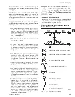
CTB1
21
13
LOAD LIMIT INPUT
14
13
FLOW SW
REMOTE START/STOP
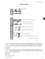
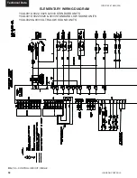
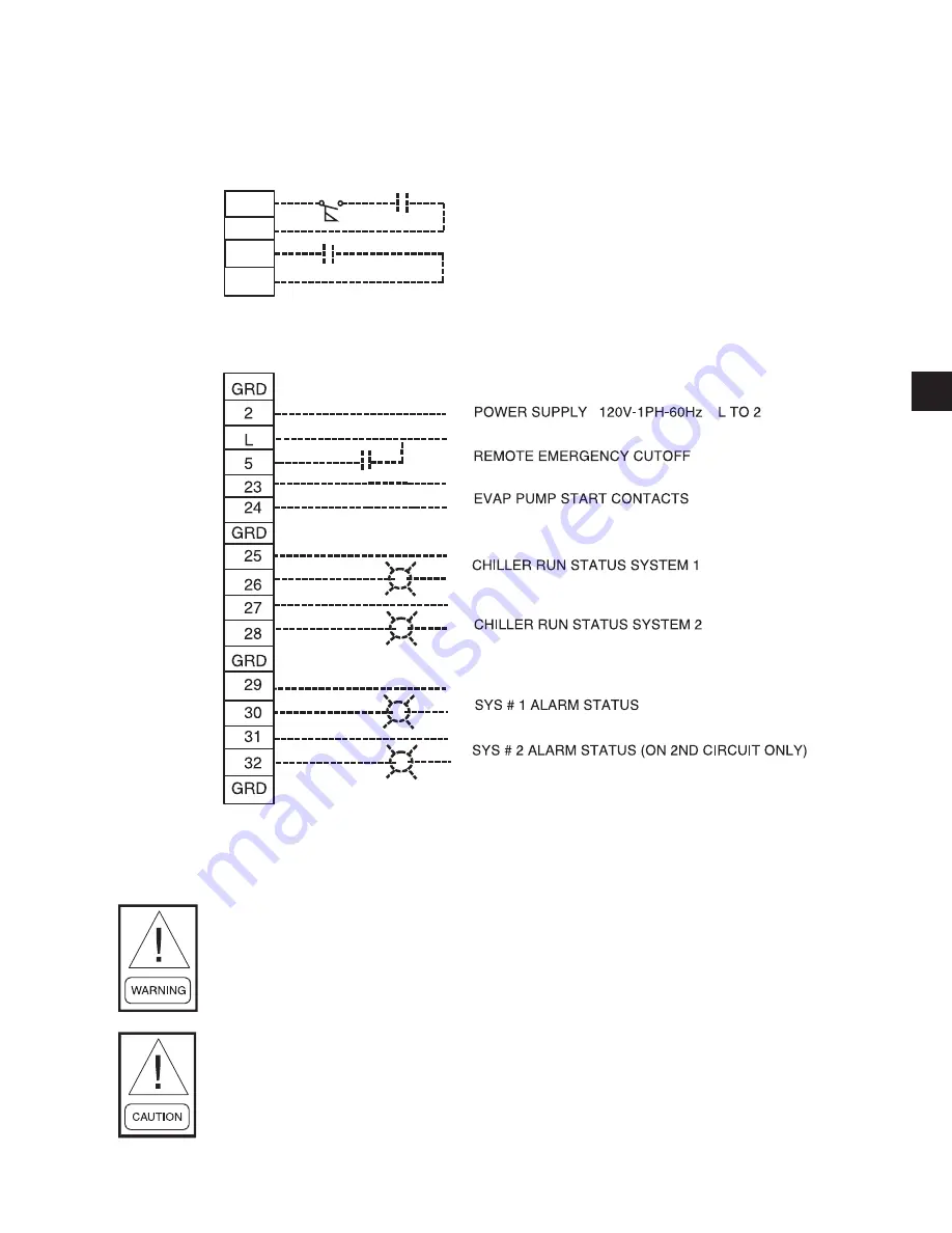
FIG. 9 –
CONTROL WIRING
CONTROL WIRING
*
* Factory wired with optional transformer.
LD07730
LD07725A
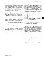
It is possible that multiple sources of power can be supplying the unit power panel. To prevent
serious injury or death, the technician should verify that NO LETHAL VOLTAGES are
present inside the panel AFTER disconnecting power, PRIOR to working on equipment.
The unit evaporator heater uses 120VAC. Disconnecting 120VAC power from the unit, at
or below freezing temperatures, can result in damage to the evaporator and unit as a result
of the chilled liquid freezing.
CTB2
Summary of Contents for YCAL0019
Page 55: ...FORM 150 67 NM2 209 55 JOHNSON CONTROLS 5 5 ELEMENTARY WIRING DIAGRAM CON T LD12699D...
Page 57: ...FORM 150 67 NM2 209 57 JOHNSON CONTROLS 5 5 ELEMENTARY WIRING DIAGRAM CON T LD12693C...
Page 59: ...FORM 150 67 NM2 209 59 JOHNSON CONTROLS 5 5 ELEMENTARY WIRING DIAGRAM CON T LD 12198...
Page 61: ...FORM 150 67 NM2 209 61 JOHNSON CONTROLS 5 5 LD12702 ELEMENTARY WIRING DIAGRAM CON T...
Page 63: ...FORM 150 67 NM2 209 63 JOHNSON CONTROLS 5 5 LD12696 ELEMENTARY WIRING DIAGRAM CON T...
Page 65: ...FORM 150 67 NM2 209 65 JOHNSON CONTROLS 5 5 CONNECTION WIRING DIAGRAM CON T LD12703B...
Page 67: ...FORM 150 67 NM2 209 67 JOHNSON CONTROLS 5 5 CONNECTION WIRING DIAGRAM CON T LD12697B...