JOHNSON CONTROLS
168
FORM 150.67-NM2 (209)
Unit Operation
General
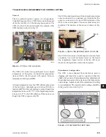
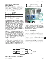
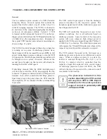
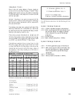
The low ambient option consists of a VFD (Variable
Frequency Drive) that controls the speed of the
fi
rst fan
(Fan 1) in the fan staging sequence. The VFD is located on
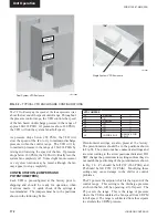
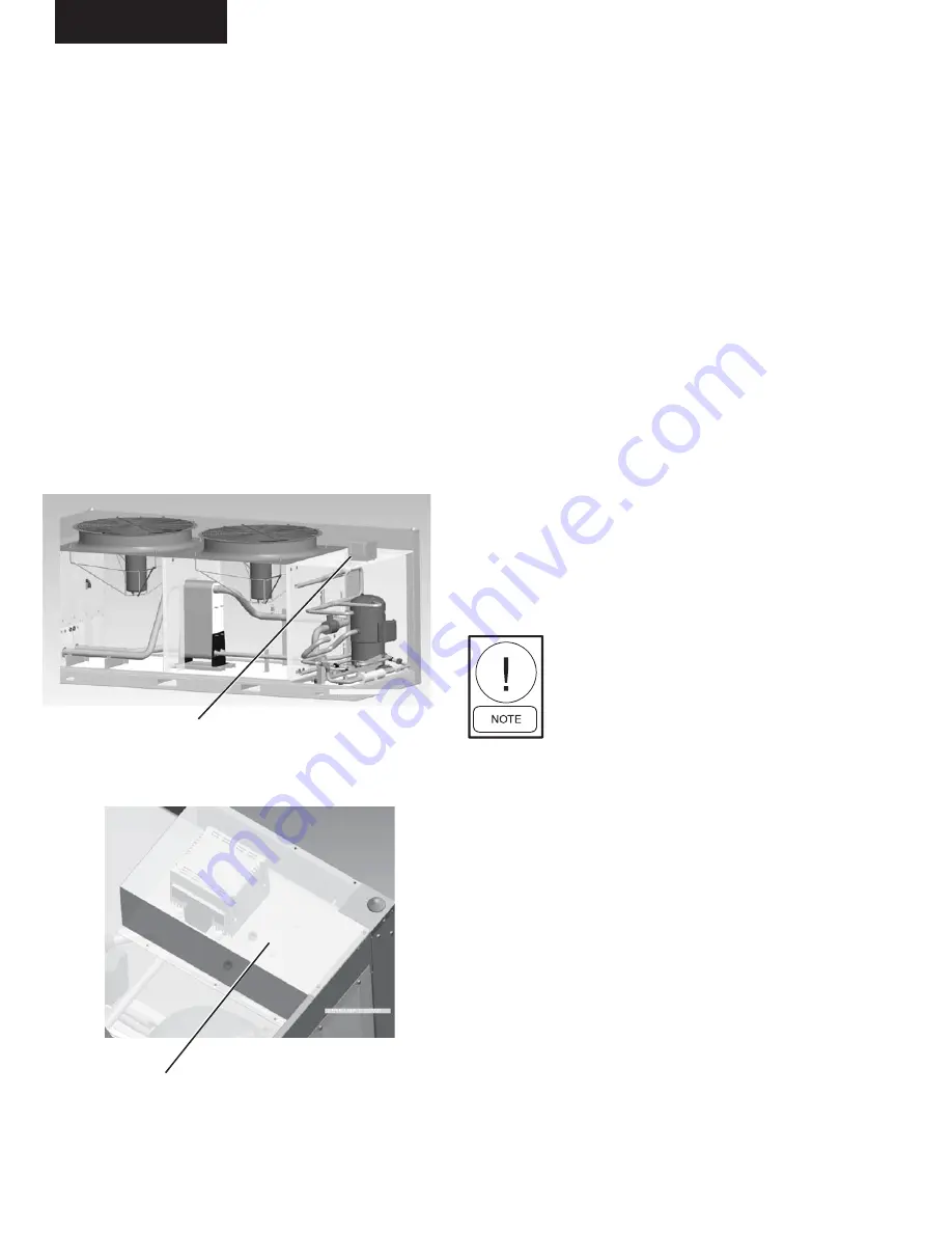
the top of chiller above the compressor section. Examples
of the typical VFD location and enclosure mountings are
shown in Figs. 26 & 27.
The VFD will control fan speed when only a single fan is
running on a system. As discharge pressure rises and falls,
the fan speed will be increased from zero RPM to full
speed. As discharge pressure continues to rise, the VFD
will operate the fan at full speed and the second fan will be
brought on in a system, if needed. Whenever the second
fan is brought on, the inverter will already be running the
fi
rst fan at full speed. When discharge pressure falls, the
chiller microprocessor will turn the second fan off by de-
energizing the fan contactor.
If pressure continues to fall, VFD speed will decrease in
an effort to maintain discharge pressure. Speed may drop
to the point where the VFD turns the fan completely off or
virtually off with a continued drop in pressure.
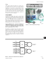
The VFD control input signal is from the discharge
pressure transducer in the respective system. The
transducer signal feeds both the chiller microprocessor
board and the VFD. The VFD controls the fan speed based
on discharge pressure.
The VFD will control the fan speed not only in low
ambient conditions, but in all ambients based on discharge
pressure. Speed control of the respective system will
occur whenever high voltage power is applied to the
VFD power inputs through the 7M contactor. The chiller
microprocessor will energize the 7M and 10M contactors
whenever the system liquid line solenoid is energized.
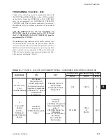
The VFD controls the speed of the fan based on a discharge
pressure setpoint and a differential control range. When
a compressor starts in a system, the inverter is activated
through the 7M contactor, which is controlled from the
respective liquid line solenoid valve control signal. At
discharge pressures below 260 PSIG, the VFD will turn the
fan off or speed will be reduced to all but small movements
in fan rotation.
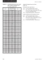
The pressures indicated in this section
describing the VFD control will vary from
VFD to VFD. Expect tolerances for the
entire pressure range of control to poten-
tially shift -0 PSIG/+24 PSIG.
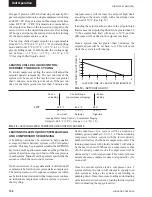
The VFD will ramp up the speed of the fan as pressure rises
above the low end of the speed control range. Throughout
the pressure control range, the VFD controls the speed of
the fan based on a discharge pressure in the range of approx
260-292 PSIG. At pressures above 292 PSIG, the VFD will
run the system fan at full speed.
As pressure drops below 292 PSIG, the VFD will slow
the speed of the fan to try to maintain discharge pressure
within the control range. The VFD will try to maintain
pressure in the range of 260-292 PSIG by raising and
lowering the speed of the fan. If pressure drops below
260 PSIG, the VFD will virtually turn the system fan
completely off. Some slight fan movement or very slow
rotation may be noted, although the fan may appear to stop
completely.
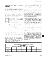
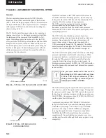
FIG. 26 –
TYPICAL VFD ENCLOSURE LOCATIONS
VFD Enclosure Location
LD12080
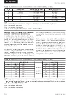
VFD Enclosure
LD12081
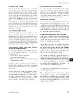
FIG. 27-
TYPICAL VFD ENCLOSURE
CONFIGURATIONS
LOW AMBIENT FAN CONTROL OPTION
YCAL0033
Summary of Contents for YCAL0019
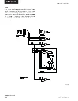
Page 55: ...FORM 150 67 NM2 209 55 JOHNSON CONTROLS 5 5 ELEMENTARY WIRING DIAGRAM CON T LD12699D...
Page 57: ...FORM 150 67 NM2 209 57 JOHNSON CONTROLS 5 5 ELEMENTARY WIRING DIAGRAM CON T LD12693C...
Page 59: ...FORM 150 67 NM2 209 59 JOHNSON CONTROLS 5 5 ELEMENTARY WIRING DIAGRAM CON T LD 12198...
Page 61: ...FORM 150 67 NM2 209 61 JOHNSON CONTROLS 5 5 LD12702 ELEMENTARY WIRING DIAGRAM CON T...
Page 63: ...FORM 150 67 NM2 209 63 JOHNSON CONTROLS 5 5 LD12696 ELEMENTARY WIRING DIAGRAM CON T...
Page 65: ...FORM 150 67 NM2 209 65 JOHNSON CONTROLS 5 5 CONNECTION WIRING DIAGRAM CON T LD12703B...
Page 67: ...FORM 150 67 NM2 209 67 JOHNSON CONTROLS 5 5 CONNECTION WIRING DIAGRAM CON T LD12697B...