


FORM 150.67-NM2 (209)
145
JOHNSON CONTROLS
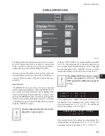
7
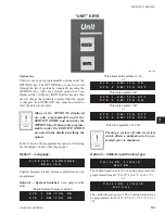
(leaving chilled liquid control)
(return chilled liquid control)
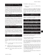
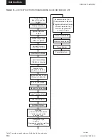
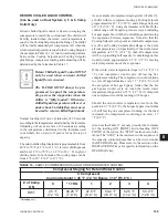
The low limit, high limit, and default values for the keys
under “SETPOINTS” are listed in Table 12.
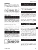
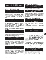
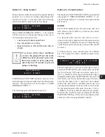
Pressing the COOLING SETPOINTS a third time will
bring up the display that allows the Maximum EMS-
PWM Temperature Reset to be programmed. This
message is shown below.
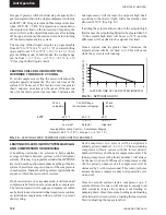
The Temp Reset value is the maximum allowable remote
reset of the temperature setpoint. The setpoint can be
reset
upwards by the use of an Energy Management
System or from the Temperature Reset Option Board.
See page 176 for a detailed explanation of this feature.
As with the other setpoints, the
↑
(UP) arrow and
↓
(DOWN) arrow keys are used to change the Temp Reset
value. After using the
↑
(UP) and
↓
(DOWN) arrows to
adjust to the desired setpoint, the ENTER/ADV key must
be pressed to enter this number into memory.
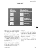
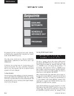
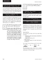
SCHEDULE/ADVANCE DAY KEY
The SCHEDULE is a seven day daily schedule that
allows one start/stop time per day. The schedule can be
programmed Monday through Sunday with an alternate
holiday schedule available. If no start/stop times are
programmed, the unit will run on demand, providing the
chiller is not shut off on a unit or system shutdown. The
daily schedule is considered “not programmed” when
the times in the schedule are all zeros (00:00 AM).
To set the schedule, press the SCHEDULE/ADVANCE
DAY
key. The display will immediately show the
following display.
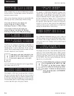
would be displayed in place of the previous message.
When in leaving chilled liquid temperature control, the
micro will attempt to control the leaving water tem-
perature within the temperature range of the se
or – the range. In the above example, control will be in
the range of 43 – 47 °F.
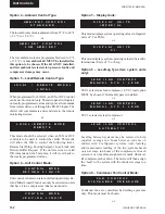
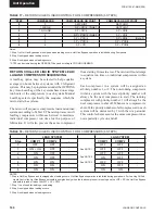
Return Chilled Liquid Control
In return chilled liquid control, the range no longer has
a +/- X.X °F, but only a + X.X °F RANGE setpoint.
This indicates that the setpoint is not centered within
the RANGE but could be described as the bottom of
the control range. A listing of the limits and the pro-
grammable values for the COOLING SETPOINTS are
shown in Table 12.
The SETPOINT and RANGE displays just described
were based on LOCAL control. If the unit was pro-
grammed for REMOTE control (under the OPTIONS
key), the above programmed setpoints would have no
effect.
When in return chilled liquid temperature control, the
micro will turn all compressors off at setpoint and will
turn compressors on as return chilled liquid tempera-
ture rises. All compressors will be on at se the
range. If the range equals the temperature drop across
the evaporator when fully loaded, the leaving chilled
liquid temperature will remain near the se or – a
few degrees as the chiller loads and unloads according
to return chilled liquid temperature.
Both LEAVING and RETURN control are described in
detail under the section on CAPACITY CONTROL.
Remote Setpoint Control
Pressing the COOLING SETPOINTS key a second
time will display the remote setpoint and cooling
range. This display automatically updates about every
2 seconds. Notice that these setpoints are not “locally”
programmable, but are controlled by a remote device
such as an ISN control, remote reset option board, or
remote PWM signal. These setpoints would only be valid
if the unit was operating in the REMOTE mode.
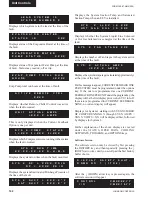
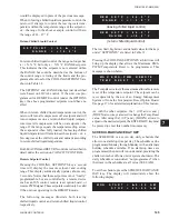
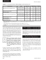
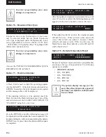
The following messages illustrate both leaving
chilled liquid control and return chilled liquid control
respectively.
R E M S E T P = 4 4 . 0 ° F
R A N G E = + / - 2 . 0 ° F
R E M S E T P = 4 4 . 0 ° F
R
A
N
G
E =
+
1
0 . 0
°
F
M A X E M S - P W M R E M O T E
T E M P R E S E T = +
2 0 ° F
S E T P O I N T = 4 5 . 0 ° F
R A N G E = +
1 0 . 0 ° F
M
O N S T A R T = 0 0 : 0 0 A
M
S
T
O
P = 0
0 : 0
0 A
M
Summary of Contents for YCAL0019
Page 55: ...FORM 150 67 NM2 209 55 JOHNSON CONTROLS 5 5 ELEMENTARY WIRING DIAGRAM CON T LD12699D...
Page 57: ...FORM 150 67 NM2 209 57 JOHNSON CONTROLS 5 5 ELEMENTARY WIRING DIAGRAM CON T LD12693C...
Page 59: ...FORM 150 67 NM2 209 59 JOHNSON CONTROLS 5 5 ELEMENTARY WIRING DIAGRAM CON T LD 12198...
Page 61: ...FORM 150 67 NM2 209 61 JOHNSON CONTROLS 5 5 LD12702 ELEMENTARY WIRING DIAGRAM CON T...
Page 63: ...FORM 150 67 NM2 209 63 JOHNSON CONTROLS 5 5 LD12696 ELEMENTARY WIRING DIAGRAM CON T...
Page 65: ...FORM 150 67 NM2 209 65 JOHNSON CONTROLS 5 5 CONNECTION WIRING DIAGRAM CON T LD12703B...
Page 67: ...FORM 150 67 NM2 209 67 JOHNSON CONTROLS 5 5 CONNECTION WIRING DIAGRAM CON T LD12697B...