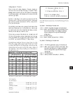

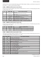
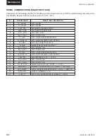

FORM 150.67-NM2 (209)
189
JOHNSON CONTROLS
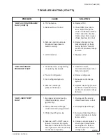
10
SECTION 10 – MAINTENANCE
It is the responsibility of the equipment owner to provide
maintenance on the system.
IMPORTANT
If system failure occurs due to improper maintenance
during the warranty period, YORK will not be liable
for costs incurred to return the system to satisfactory
operation. The following is intended only as a guide and
covers only the chiller unit components. It does not cover
other related system components which may or may not
be furnished by YORK. System components should be
maintained according to the individual manufacture’s
recommendations as their operation will affect the
operation of the chiller.
COMPRESSORS
Oil Level check
The oil level can only be tested when the compressor is
running in stabilized conditions, to ensure that there is
no liquid refrigerant in the lower shell of the compressor.
When the compressor is running at stabilized conditions,
the oil level must be between 1/4 and 3/4 in the oil sight
glass. Note: at shutdown, the oil level can fall to the
bottom limit of the oil sight glass. Use YORK “V” oil
when adding oil.
Oil Analysis
The oil used in these compressors is pale yellow in color
(POE oil). If the oil color darkens or exhibits a change in
color, this may be an indication of contaminants in the
refrigerant system. If this occurs, an oil sample should
be taken and analyzed. If contaminants are present, the
system must be cleaned to prevent compressor failure.
Never use the scroll compressor to
pump the refrigerant system down into
a vacuum. Doing so will cause internal
arcing of the compressor motor which
will result in failure of compressor.
CONDENSER FAN MOTORS
Condenser fan motors are permanently lubricated and
require no maintenance.
CONDENSER COILS
Dirt should not be allowed to accumulate on the
condenser coil surfaces. Cleaning should be as often as
necessary to keep coils clean.
Exercise care when cleaning the coil
so that the coil fi ns are not damaged.
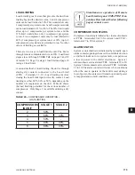
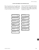
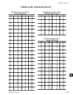
OPERATING PARAMETERS
Regular checks of the system should be preformed to
ensure that operating temperatures and pressures are
within limitations, and that the operating controls are set
within proper limits. Refer to the Operation, Start-Up,
and Installation sections of this manual.
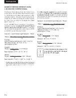
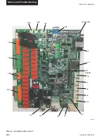
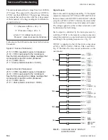
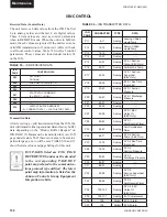
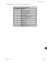
ON-BOARD BATTERY BACK-UP
U5 is the Real Time Clock chip located on the 031-
02630 IPU II board that maintains the date/time and
stores customer programmed setpoints. The Real Time
Clock is a 128K bram, P/N 031-02565-000. The IPU
II board must have JP1 installed when the 128K bram
is installed.
Do not confuse JP1 on the IPU II
(031-02630) board with JP1 on the I/O
(031-02550) board.
PLATE AND FRAME HEAT EXCHANGER
(EVAPORATOR) HEATER
The Plate and Frame Heat Exchang-
er (evaporator) heater is 120VAC.
Disconnecting 120VAC power from
the unit, at or below freezing tem-
peratures, can result in damage to the
evaporator and unit as a result of the
chilled liquid freezing.
OVERALL UNIT INSPECTION
In addition to the checks listed on this page, periodic
overall inspections of the unit should be accomplished
to ensure proper equipment operation. Items such as
loose hardware, component operation, refrigerant leaks,
unusual noises, etc. should be investigated and corrected
immediately.
Summary of Contents for YCAL0019
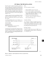
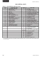
Page 55: ...FORM 150 67 NM2 209 55 JOHNSON CONTROLS 5 5 ELEMENTARY WIRING DIAGRAM CON T LD12699D...
Page 57: ...FORM 150 67 NM2 209 57 JOHNSON CONTROLS 5 5 ELEMENTARY WIRING DIAGRAM CON T LD12693C...
Page 59: ...FORM 150 67 NM2 209 59 JOHNSON CONTROLS 5 5 ELEMENTARY WIRING DIAGRAM CON T LD 12198...
Page 61: ...FORM 150 67 NM2 209 61 JOHNSON CONTROLS 5 5 LD12702 ELEMENTARY WIRING DIAGRAM CON T...
Page 63: ...FORM 150 67 NM2 209 63 JOHNSON CONTROLS 5 5 LD12696 ELEMENTARY WIRING DIAGRAM CON T...
Page 65: ...FORM 150 67 NM2 209 65 JOHNSON CONTROLS 5 5 CONNECTION WIRING DIAGRAM CON T LD12703B...
Page 67: ...FORM 150 67 NM2 209 67 JOHNSON CONTROLS 5 5 CONNECTION WIRING DIAGRAM CON T LD12697B...