


FORM 150.67-NM2 (209)
185
JOHNSON CONTROLS
9
LD12723
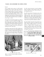
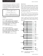
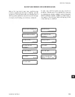
The micro panel is capable of supplying a printout of
chiller conditions or fault shutdown information at any
given time. This allows operator and service personnel
to obtain data and system status with the touch of the
keypad. In addition to manual print selection, the micro
panel will provide an automatic printout whenever a
fault occurs. Detailed explanation of the print function
is given under “Print Key” located in the Keypad and
Display section.
YORK recommends the
fi
eld tested WEIGH-TRONIX
model 1220 printer (or former IMP 24). This is a com-
pact low cost printer that is ideal for service work and
data logging.
The WEIGH-TRONIX printer can be obtained by con-
tacting WEIGH-TRONIX for purchase information at:
WEIGH-TRONIX
2320 Airport Blvd.
Santa Rosa, CA 95402
Phone: 1-800-982-6622 or 1-707-527-5555
(International Orders Only)
The part number for the printer that is packaged speci
fi
-
cally for YORK is P/N 950915576. The cable to connect
the printer can either be locally assembled from the parts
listed, or ordered directly from WEIGH-TRONIX under
part number 287-040018.
Parts
The following parts are required:
1. WEIGH-TRONIX model 1220 printer.
2. 2.25” (5.7cm) wide desk top calculator paper.
3. 25 ft. (7.62m) maximum length of Twisted Pair
Shielded Cable (minimum 3 conductor), #18 AWG
stranded, 300V minimum insulation.
4. One 25 pin Cannon connector and shell.
Connector: Cannon P/N DB-25P or equivalent.
Shell: Cannon P/N DB-C2-J9.
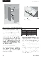
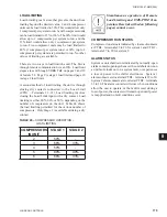
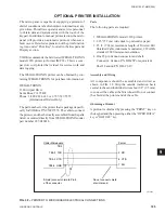
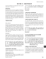
Assembly and Wiring
All components should be assembled and wired as
shown in FIG. 38. Strip the outside insulation back
several inches and individual wires about 3/8” (9.5 mm)
to connect the cable at the Microboard. Do not connect
the shield at the printer-end of the cable.
Obtaining a Printout
A printout is obtained by pressing the “PRINT” key on
the keypad and then pressing either the “OPER DATA”
key or “HISTORY” key.
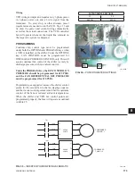
FIG. 38 –
PRINTER TO MICROBOARD ELECTRICAL CONNECTIONS
OPTIONAL PRINTER INSTALLATION
TB3-3 TXD
TB3-2 CTS
TB3-5 GND
TB3
2 RD
7 SG
5 CTS
Chiller Microboard
Printer
Do not connect shield
at printer end.
Shield (connect shield to Pin 5
of the connector.
Summary of Contents for YCAL0019
Page 55: ...FORM 150 67 NM2 209 55 JOHNSON CONTROLS 5 5 ELEMENTARY WIRING DIAGRAM CON T LD12699D...
Page 57: ...FORM 150 67 NM2 209 57 JOHNSON CONTROLS 5 5 ELEMENTARY WIRING DIAGRAM CON T LD12693C...
Page 59: ...FORM 150 67 NM2 209 59 JOHNSON CONTROLS 5 5 ELEMENTARY WIRING DIAGRAM CON T LD 12198...
Page 61: ...FORM 150 67 NM2 209 61 JOHNSON CONTROLS 5 5 LD12702 ELEMENTARY WIRING DIAGRAM CON T...
Page 63: ...FORM 150 67 NM2 209 63 JOHNSON CONTROLS 5 5 LD12696 ELEMENTARY WIRING DIAGRAM CON T...
Page 65: ...FORM 150 67 NM2 209 65 JOHNSON CONTROLS 5 5 CONNECTION WIRING DIAGRAM CON T LD12703B...
Page 67: ...FORM 150 67 NM2 209 67 JOHNSON CONTROLS 5 5 CONNECTION WIRING DIAGRAM CON T LD12697B...