JOHNSON CONTROLS
170
FORM 150.67-NM2 (209)
Unit Operation
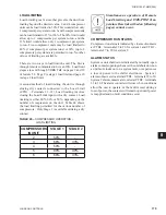
TB3
TB1
TB2
TO PANEL 7M
TO FAN #1 (EXISTING HARNESS)
TO MICROBOARD (P4)
151
150
152
150A
151A
152A
WHT
BLK
TB3
TB1
TB2
TB3
TB1
TB2
TO PANEL 7M
TO FAN #1 (EXISTING HARNESS)
TO MICROBOARD (P4)
151
150
152
150A
151A
152A
WHT
BLK
LD11302a
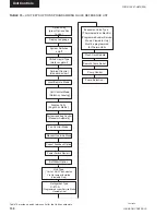
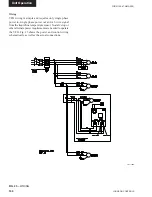
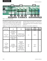
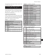
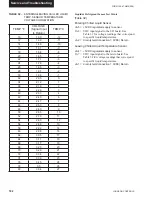
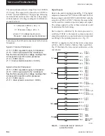
FIG. 30 –
INVERTER WIRING
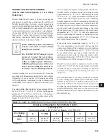
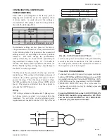
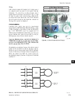
Programming as suggested assures the chiller control
points for the second fan in the fan staging sequence
and the inverter control points are matched for optimum
control of the fans at reduced ambient temperatures,
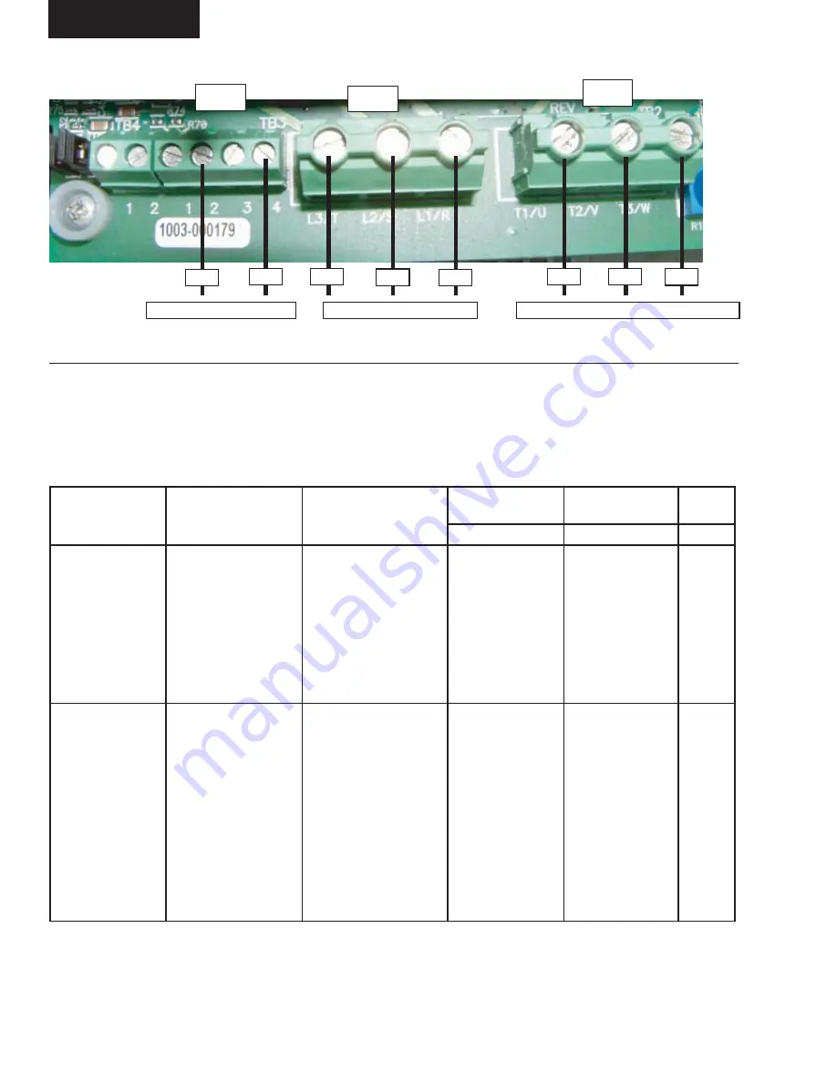
FAN STAGE
ON
OFF
CONTACTOR
MICRO
BOARD
FAN #
SYS 1
SYS 1
SYS 1
1:
VFD Control
(1 fan
Variable Speed)
Fan Speed
Is A Function Of
Discharge
Pressure.
When The Liquid
Line Solenoid Is
Energized. Speed
Increases With
Pressure
FAN Will Turn Off
or Turn Very Slowly
When Pressure Drops
Below 260 PSIG.
7M
TB7-3
1
2:
1 Fan VFD
Control
2nd Fan
Full Speed
Under Contactor
Control
425 PSIG,
Both Fans
Will Be Running Full
Speed
Discharge
Pressure
< 260 PSIG (Pres-
sure Is
< Fan Control ON
Pressure of
425 PSIG Minus Fan
Differential
Pressure of 125
PSIG = 300 PSIG)
7M
&
8M
TB7-3
&
TB7-10
3
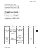
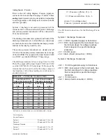
assuring superheat and oil control is not compromised.
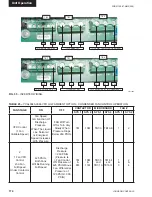
When the chiller and VFD fan control points are
programmed properly, the fans will operate as outlined
in Table 24.
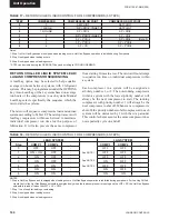
TABLE 24 –
YCAL033 VFD LOW AMBIENT OPTION – CONDENSER FAN CONTROL OPERATION
Summary of Contents for YCAL0019
Page 55: ...FORM 150 67 NM2 209 55 JOHNSON CONTROLS 5 5 ELEMENTARY WIRING DIAGRAM CON T LD12699D...
Page 57: ...FORM 150 67 NM2 209 57 JOHNSON CONTROLS 5 5 ELEMENTARY WIRING DIAGRAM CON T LD12693C...
Page 59: ...FORM 150 67 NM2 209 59 JOHNSON CONTROLS 5 5 ELEMENTARY WIRING DIAGRAM CON T LD 12198...
Page 61: ...FORM 150 67 NM2 209 61 JOHNSON CONTROLS 5 5 LD12702 ELEMENTARY WIRING DIAGRAM CON T...
Page 63: ...FORM 150 67 NM2 209 63 JOHNSON CONTROLS 5 5 LD12696 ELEMENTARY WIRING DIAGRAM CON T...
Page 65: ...FORM 150 67 NM2 209 65 JOHNSON CONTROLS 5 5 CONNECTION WIRING DIAGRAM CON T LD12703B...
Page 67: ...FORM 150 67 NM2 209 67 JOHNSON CONTROLS 5 5 CONNECTION WIRING DIAGRAM CON T LD12697B...