


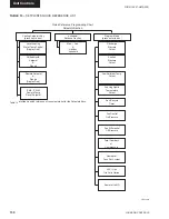

FORM 150.67-NM2 (209)
143
JOHNSON CONTROLS
7
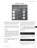
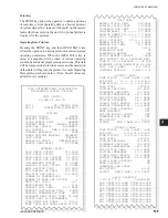
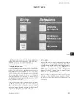
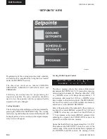
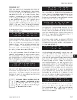
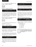
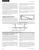
The Entry Keys allows the user to view, change programmed
values. The ENTRY keys consist of an
↑
(UP) arrow key,
↓
(DOWN) arrow key, and an ENTER/ADV key.
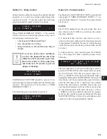
Up and Down Arrow Keys
Used in conjunction with the OPER DATA, HISTORY,
COOLING SETPOINTS, SCHEDULE/ADVANCE
DAY, OPTIONS and CLOCK keys, the
↑
(UP) and
↓
(DOWN) arrow keys allow the user to scroll through
the various data screens. Refer to the section on
“DISPLAY/PRINT” keys for speci
fi
c information on
the displayed information and speci
fi
c use of the
↑
(UP)
and
↓
(DOWN) arrow keys.
The
↑
(UP) arrow key, and
↓
(DOWN) arrow key are also
used for programming the control panel such as changing
numerical or text values when programming cooling
setpoints, setting the daily schedule, changing safety
setpoints, chiller options, and setting the clock.
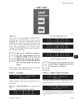
“ENTRY” KEYS
Enter/adv Key
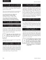
The ENTER/ADV key must be pushed after any change
is made to the cooling setpoints, daily schedule, safety
setpoints, chiller options, and the clock. Pressing this key
“enters” the new values into memory. If the ENTER/
ADV key is not pressed after a value is changed, the
changes will not be “entered” and the original values
will be used to control the chiller.
Programming and a description on the use of the
↑
(UP)
arrow key, and
↓
(DOWN) arrow, and ENTER/ADV
keys are covered in detail under the SETPOINTS, and
UNIT keys.
00068VIP
Summary of Contents for YCAL0019
Page 55: ...FORM 150 67 NM2 209 55 JOHNSON CONTROLS 5 5 ELEMENTARY WIRING DIAGRAM CON T LD12699D...
Page 57: ...FORM 150 67 NM2 209 57 JOHNSON CONTROLS 5 5 ELEMENTARY WIRING DIAGRAM CON T LD12693C...
Page 59: ...FORM 150 67 NM2 209 59 JOHNSON CONTROLS 5 5 ELEMENTARY WIRING DIAGRAM CON T LD 12198...
Page 61: ...FORM 150 67 NM2 209 61 JOHNSON CONTROLS 5 5 LD12702 ELEMENTARY WIRING DIAGRAM CON T...
Page 63: ...FORM 150 67 NM2 209 63 JOHNSON CONTROLS 5 5 LD12696 ELEMENTARY WIRING DIAGRAM CON T...
Page 65: ...FORM 150 67 NM2 209 65 JOHNSON CONTROLS 5 5 CONNECTION WIRING DIAGRAM CON T LD12703B...
Page 67: ...FORM 150 67 NM2 209 67 JOHNSON CONTROLS 5 5 CONNECTION WIRING DIAGRAM CON T LD12697B...