

JOHNSON CONTROLS
158
FORM 150.67-NM2 (209)
Unit Operation
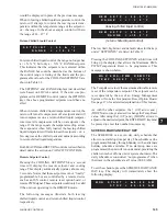
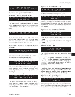
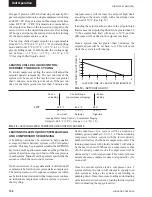
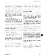
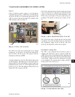
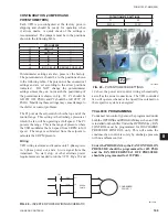
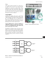
FIG. 18 –
LEAVING WATER TEMPERATURE CONTROL EXAMPLE
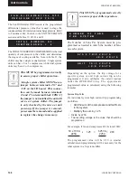
Hot gas, if present, will be the
fi
nal step of capacity. Hot
gas is energized when only a single compressor is running
and LWT<SP. Hot gas is turned off as temperature rises
when LWT>SP + CR/2. If temperature remains below
the setpoint low limit on the lowest step of capacity, the
micro will close the liquid line solenoid, after turning
off hot gas, and pump the system down before turning
off the last compressor in a system.
The leaving chilled liquid setpoint is programmable
from 40 °F to 70 °F (4.4 °C to 21.1 °C) in water chilling
mode and from 10 °F to 70 °F (-12.2 °C to 21.1 °C) in
glycol chilling mode. In both modes, the cooling range
can be from +/-1.5 °F to +/-2.5 °F (+/-.83 °C to 1.39
°C).leaving chilled liquid control
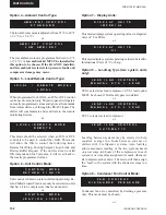
LEAVING CHILLED LIQUID CONTROL
OVERRIDE TO REDUCE CYCLING
To avoid compressor cycling the micro will adjust the
setpoint upward temporarily. The last run time of the
system will be saved. If the last run time was greater
than 5 minutes, no action is to be taken. If the last run
time for the lead system was less than 5 minutes, the
Leaving Water Temp. Control – Compressor Staging
Setpoint = 46.0 °F (7.8 °C) Range = +/- 2 °F(1.1 °C)
30 sec.
Control Range
60 sec.
unloading
(no compressor staging)
loading
44.0
°F
46.0
°F
48.0°
(6.7
°C)
(7.8
°C)
(8.9
°C)
Low Limit
Setpoint
High limit
LWT
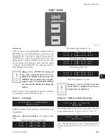
LEAVING CHILLED LIQUID SYSTEM LEAD/LAG
AND COMPRESSOR SEQUENCING
A Lead/Lag option may be selected to help equalize
average run hours between systems with 2 refrigerant
systems. This may be programmed under the OPTIONS
key. Auto Lead/Lag allows automatic Lead/Lag of the two
systems based on average run hours of the compressors
in each system. Manual Lead/Lag selects speci
fi
cally the
sequence which the micro starts systems.
On a hot water start, once a system starts, it will turn on all
compressors before the next system starts a compressor.
The microprocessor will sequence compressors within
each circuit to maximize individual compressor run time
on individual compressors within a system to prevent
short cycling.
Each compressor in a system will be assigned an
arbitrary priority number 1, 2, or 1, 2, 3. The non-running
compressor within a system with the lowest priority
number will always be the next compressor to start. The
running compressor with priority number 1 will always
be the next to shut off. Whenever a compressor is shut
off, the priority numbers of all compressors will be
decreased by 1 with wrap-around. This control scheme
assures the same compressor does not repeatedly cycle
on and off.
Once the second system starts a compressor on a 2
system chillers, the micro will attempt to equally load
each system as long as the system is not limiting or
pumping down. Once this occurs, loading and unloading
will alternate between systems, loading the lead system
fi
rst or unloading the lag system
fi
rst.
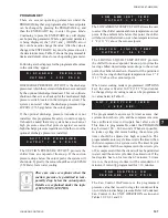
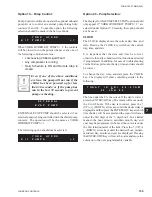
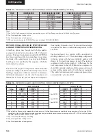
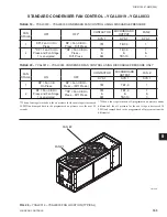
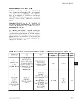
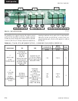
0 1
2
3
4
5
6
LAST RUN TIME OF LEAD SYSTEM (MINUTES)
SETPOINT
ADJUST
(DEG. F)
6
5
4
3
2
1
0
FIG. 19 –
SETPOINT ADJUST
microprocessor will increase the setpoint high limit
according to the chart at right, with a maximum value
allowed of 50 °F (See Fig. 19).
If adding the setpoint adjust value to the setpoint high
limit causes the setpoint high limit to be greater than 50
°F, the setpoint high limit will be set to 50 °F, and the
difference will be added to the setpoint low limit.
Once a system runs for greater than 5 minutes, the
setpoint adjust will be set back to 0. This will occur
while the system is still running.
Summary of Contents for YCAL0019
Page 55: ...FORM 150 67 NM2 209 55 JOHNSON CONTROLS 5 5 ELEMENTARY WIRING DIAGRAM CON T LD12699D...
Page 57: ...FORM 150 67 NM2 209 57 JOHNSON CONTROLS 5 5 ELEMENTARY WIRING DIAGRAM CON T LD12693C...
Page 59: ...FORM 150 67 NM2 209 59 JOHNSON CONTROLS 5 5 ELEMENTARY WIRING DIAGRAM CON T LD 12198...
Page 61: ...FORM 150 67 NM2 209 61 JOHNSON CONTROLS 5 5 LD12702 ELEMENTARY WIRING DIAGRAM CON T...
Page 63: ...FORM 150 67 NM2 209 63 JOHNSON CONTROLS 5 5 LD12696 ELEMENTARY WIRING DIAGRAM CON T...
Page 65: ...FORM 150 67 NM2 209 65 JOHNSON CONTROLS 5 5 CONNECTION WIRING DIAGRAM CON T LD12703B...
Page 67: ...FORM 150 67 NM2 209 67 JOHNSON CONTROLS 5 5 CONNECTION WIRING DIAGRAM CON T LD12697B...