


JOHNSON CONTROLS
154
FORM 150.67-NM2 (209)
Unit Controls
Incorrect programming may cause
damage to compressors.
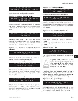
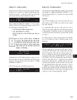
Option 16 – Expansion Valve Type:
Expansion valve type, thermostatic or electronic
may be selected under Service Mode. Expansion
valve type is displayed under the Options key, but is
only programmable in Service Mode. YCAL 0019
– 0066 chillers will typically always be equipped with
thermostaic expansion valves.
Incorrect programming may cause
damage to compressors.
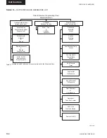
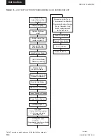
Also see the UNIT KEYS PROGRAMMING QUICK
REFERENCE LIST in Table 15.
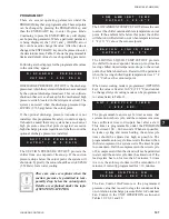
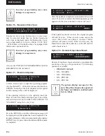
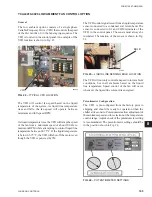
Option 17 – Flash Card Update:
A Flash Card is used to input the operating program
into the chiller IPU. A Flash Card is used instead of an
EPROM. Normally, a Flash Card update is not required
and the message above will be displayed.
If the operating software is to be updated, insert the
Flash Card into the Flash Card input port. Turn off the
unit switch and set the FLASH CARD UPDATE TO
“ENABLED” using the
↑
and
↓
keys.
Press the ENTER key and the following message will
be displayed until the update has been completed. The
keypad and display will not respond during the update.
DO NOT reset or power down the chiller until the update
is completed.
After the update is completed, an automatic reboot will
occur. If an error occurred, the following message will
appear with the error code and no reboot will occur:
If the update resulted in an error, the original program
will still be active. When an error occurs, assure the
correct Flash Card was utilized. Incorrect chiller
software will cause an error. If this is not the case, the
Flash Card is most likely defective or the IPU and I/O
combo board is bad.
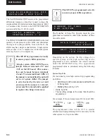
Option 18 – Remote Temperature Reset:
Remote Temp Reset input selection is programmable
according to the type of input utilized. The following
options are available:
• DISABLED (default)
• 0.0 – 10.0 (DC)
• 2.0 – 10.0V (DC)
• 0.0 – 20.0 mA
• 4.0 – 20.0 mA
The options display message for Re-
mote Temp Reset Input only appears if
the Temp reset Option is enabled under
Service Mode.
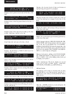
E X P A N S I O N V A L V E T Y P E
T H E R M O S T A T I C
F L A S H C A R D U P D A T I N G
P L E A S E W A I T . . .
F L A S H C A R D U P D A T E
E R R O R XXXXX
F L A S H C A R D U P D A T E
D
I
S
A
B
L
E
D
F L A S H C A R D U P D A T E
E
N
A
B
L
E
D
R E M O T E T E M P R E S E T
I N P U T XXXXXXXXXXXXXX
Summary of Contents for YCAL0019
Page 55: ...FORM 150 67 NM2 209 55 JOHNSON CONTROLS 5 5 ELEMENTARY WIRING DIAGRAM CON T LD12699D...
Page 57: ...FORM 150 67 NM2 209 57 JOHNSON CONTROLS 5 5 ELEMENTARY WIRING DIAGRAM CON T LD12693C...
Page 59: ...FORM 150 67 NM2 209 59 JOHNSON CONTROLS 5 5 ELEMENTARY WIRING DIAGRAM CON T LD 12198...
Page 61: ...FORM 150 67 NM2 209 61 JOHNSON CONTROLS 5 5 LD12702 ELEMENTARY WIRING DIAGRAM CON T...
Page 63: ...FORM 150 67 NM2 209 63 JOHNSON CONTROLS 5 5 LD12696 ELEMENTARY WIRING DIAGRAM CON T...
Page 65: ...FORM 150 67 NM2 209 65 JOHNSON CONTROLS 5 5 CONNECTION WIRING DIAGRAM CON T LD12703B...
Page 67: ...FORM 150 67 NM2 209 67 JOHNSON CONTROLS 5 5 CONNECTION WIRING DIAGRAM CON T LD12697B...