

JOHNSON CONTROLS
178
FORM 150.67-NM2 (209)
Service and Troubleshooting
Pressing the
↑
(UP) arrow key will energize the liquid
line solenoid valve and “OFF” will change to “ON” in
the display as the LLSV is energized. Energizing and
de-energizing outputs may be useful during trouble-
shooting.
SERVICE MODE – CHILLER CONFIGURATION
After the Outputs are displayed, the next group of
displays relate to chiller con
fi
guration and start/hour
counters. Data logging, soft start, refrigerant type, pump
control selection and expansion valve type all must be
programmed to match actual chiller con
fi
guration.
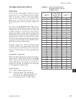
Soft start (disabled), Refrigerant Type
(R410A), and Expansion Valve Type
(Thermostatic), and North American
Feature (Enabled) MUST be properly
programmed or damage to compres-
sors and other system components
may result.
Following is a list of chiller con
fi
guration selections, in
order of appearance:
DATA LOGGING MODE = : DO NOT MODIFY
DATA LOGGING TIMER = : DO NOT MODIFY
SOFT START
REFRIGERANT TYPE
EXPANSION VALVE TYPE
REMOTE TEMP RESET OPTION
REMOTE INPUT SERVICE TIME
FEATURE SET
PUMP CONTROL SELECTION
SYS 1 HOURS
SYS 2 HOURS
SYS 1 STARTS
SYS 2 STARTS
The last displays shown on the above list are for the ac-
cumulated run and start timers for each system. All val-
ues can also be changed using the
↑
(UP) and
↓
(Down)
arrow keys, but under normal circumstances would not
be required or advised. After the last start display, the
micro will display the
fi
rst programmable value under
the PROGRAM key.
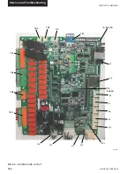
SERVICE MODE – ANALOG & DIGITAL
INPUTS
After entering Service Mode (PROGRAM
,
all digital and analog inputs to the microboard can be
viewed by pressing the OPER DATA key.
After pressing
the OPER DATA key, the
↑
(UP) arrow and
↓
(DOWN)
arrow keys are used to scroll through the analog and
digital inputs.
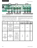
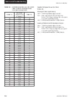
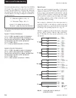
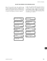
Following is the order of analog and digital inputs that
will appear when sequenced with the
Down) arrow
key:
(analog inputs)
SYS 1 SUCT PRESSURE
UNIT TYPE
SYS 1 *DISCH PRESSURE
SYS 1** SUCTION TEMP.
SYS 2** SUCTION TEMP.
AMBIENT AIR TEMP.
LEAVING LIQUID TEMP.
RETURN LIQUID TEMP.
SYS 2 SUCTION PRESSURE
SYS 2 SPARE
SYS 2 *DISCH PRESSURE
SYS 1 MTR VOLTS
SYS 2 MTR VOLTS
(digital inputs)
PWM TEMP RESET INPUT
LOAD LIMIT INPUT
FLOW SW / REM START
SPARE
SINGLE SYSTEM SELECT
SYS 1 MP / HPCO INPUT
SYS 2 MP / HPCO INPUT
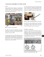
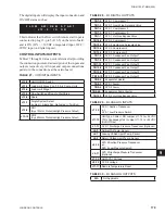
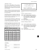
The analog inputs will display the input connection,
the temperature or pressure, and corresponding input
voltage such as:
This example indicates that the system 1 suction
pressure input is connected to plug 7 – pin 10 (J7-10)
on the I/O board. It indicates that the voltage is 2.1
volts dc which corresponds to 81 PSIG (5.6 bars)
suction pressure.
S Y S 1 S U C T P R J 7 - 1 0
2 . 1 V D C = 8 1 P S I G
* The discharge pressure transducer is optional on some models.
** The suction temp. sensor is on EEV units only.
Summary of Contents for YCAL0019
Page 55: ...FORM 150 67 NM2 209 55 JOHNSON CONTROLS 5 5 ELEMENTARY WIRING DIAGRAM CON T LD12699D...
Page 57: ...FORM 150 67 NM2 209 57 JOHNSON CONTROLS 5 5 ELEMENTARY WIRING DIAGRAM CON T LD12693C...
Page 59: ...FORM 150 67 NM2 209 59 JOHNSON CONTROLS 5 5 ELEMENTARY WIRING DIAGRAM CON T LD 12198...
Page 61: ...FORM 150 67 NM2 209 61 JOHNSON CONTROLS 5 5 LD12702 ELEMENTARY WIRING DIAGRAM CON T...
Page 63: ...FORM 150 67 NM2 209 63 JOHNSON CONTROLS 5 5 LD12696 ELEMENTARY WIRING DIAGRAM CON T...
Page 65: ...FORM 150 67 NM2 209 65 JOHNSON CONTROLS 5 5 CONNECTION WIRING DIAGRAM CON T LD12703B...
Page 67: ...FORM 150 67 NM2 209 67 JOHNSON CONTROLS 5 5 CONNECTION WIRING DIAGRAM CON T LD12697B...