


FORM 150.67-NM2 (209)
133
JOHNSON CONTROLS
7
Unit Safeties
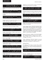
Unit safeties are faults that cause all running compressors
to be shut down. Unit faults are auto reset faults in that
the unit will be allowed to restart automatically after the
fault condition is no longer present.
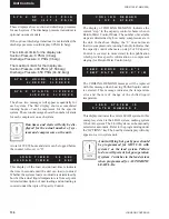
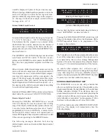
The Low Ambient Temp Cutout is a safety shutdown
designed to protect the chiller from operating in a low
ambient condition. If the outdoor ambient temperature
falls below the programmable cutout, the chiller will
shut down. Restart can occur when temperature rises 2
°F above the cutoff.
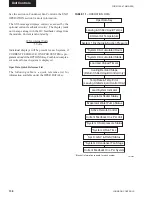
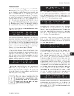
The Low Leaving Chilled Liquid Temp Cutout protects
the chiller form an evaporator freeze-up should the
chilled liquid temperature drop below the freeze point.
This situation could occur under low
fl
ow conditions
or if the micro panel setpoint values are improperly
programmed. Anytime the leaving chilled liquid
temperature (water or glycol) drops below the cutout
point, the chiller will shutdown. Restart can occur when
chilled liquid temperature rises 2 °F above the cutout.
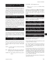
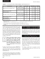
The Under Voltage Safety assures that the system is
not operated at voltages where malfunction of the
microprocessor could result in system damage. When the
115VAC to the micro panel drops below a certain level, a
unit fault is initiated to safely shut down the unit. Restart
is allowed after the unit is fully powered again and the
anti-recycle timers have
fi
nished counting down.
When the CURRENT FEEDBACK ONE PER UNIT
option is selected under the OPTIONS Key, the unit will
shut down when the voltage exceeds the programmed
trip voltage for 5 seconds.
The trip voltage is programmed at the factory according
to compressor or unit RLA.
Restart will occur after the anti-recycle timer times
out.
Unit Warning
The following messages are not unit safeties and
will not be logged to the history buffer. They are
unit
warnings
and will not auto-restart. Operator intervention
is required to allow a restart of the chiller.
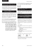
The Low Battery Warning can only occur at unit
power-up. On micro panel power-up, the RTC battery
is checked. If a low battery is found, all programmed
setpoints, program values, options, time, schedule, and
history buffers will be lost. These values will all be reset
to their default values which may not be the desired
operating values. Once a faulty battery is detected,
the unit will be prevented from running until the
PROGRAM key is pressed. Once PROGRAM is pressed
the anti-recycle timers will be set to the programmed
anti-recycle time to allow the operator time to check
setpoints, and if necessary, reprogram programmable
values and options.
If a low battery is detected, it should be replaced as
soon as possible. The programmed values will all be lost
and the unit will be prevented from running on the next
power interruption. The RTC/battery (031-00955-000)
is located at U17 on the microboard.
This indicates the condensing unit jumper is installed
on J11-12. This jumper must be removed to operate the
chiller.
U N I T F A U L T :
L O W A M B I E N T T E M P
U
N
I T F
A
U
L
T
:
1 1 5 V A C U N D E R V O L T A G E
U
N
I T F
A
U
L
T
:
L O
W L I Q U I D T E M P
! ! L
O
W B
A
T T
E
R
Y ! !
C H E C K P R O G / S E T P / O P T N
U N I T F A U L T :
H I G H M T R C U R R
I N C O R R E C T
U N I T T Y P E
Summary of Contents for YCAL0019
Page 55: ...FORM 150 67 NM2 209 55 JOHNSON CONTROLS 5 5 ELEMENTARY WIRING DIAGRAM CON T LD12699D...
Page 57: ...FORM 150 67 NM2 209 57 JOHNSON CONTROLS 5 5 ELEMENTARY WIRING DIAGRAM CON T LD12693C...
Page 59: ...FORM 150 67 NM2 209 59 JOHNSON CONTROLS 5 5 ELEMENTARY WIRING DIAGRAM CON T LD 12198...
Page 61: ...FORM 150 67 NM2 209 61 JOHNSON CONTROLS 5 5 LD12702 ELEMENTARY WIRING DIAGRAM CON T...
Page 63: ...FORM 150 67 NM2 209 63 JOHNSON CONTROLS 5 5 LD12696 ELEMENTARY WIRING DIAGRAM CON T...
Page 65: ...FORM 150 67 NM2 209 65 JOHNSON CONTROLS 5 5 CONNECTION WIRING DIAGRAM CON T LD12703B...
Page 67: ...FORM 150 67 NM2 209 67 JOHNSON CONTROLS 5 5 CONNECTION WIRING DIAGRAM CON T LD12697B...