
FORM 150.67-NM2 (209)
179
JOHNSON CONTROLS
9
F L O
W S
W / R E M S T A R T
J
13
- 5 I
S O
N
TABLE 30
– I/O ANALOG OUTPUTS
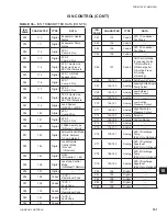
TABLE 29
– I/O ANALOG INPUTS
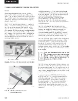
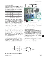
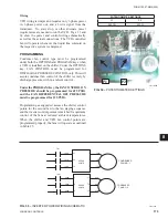
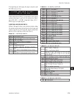
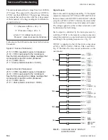
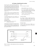
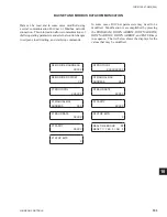
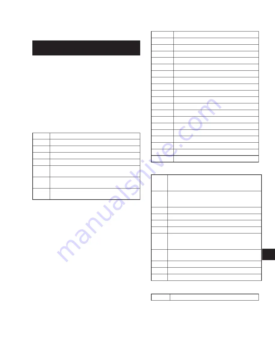
The digital inputs will display the input connection and
ON/OFF status such as:
This indicates that the
fl
ow switch/remote start input is
connected to plug 13- pin 5 (J13-5) on the microboard,
and is ON (ON = +30VDC unregulated input, OFF =
0VDC input on digital inputs).
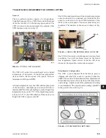
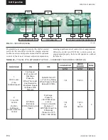
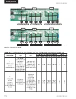
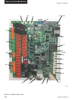
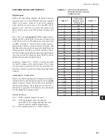
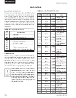
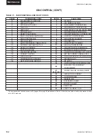
CONTROL INPUTS/OUTPUTS
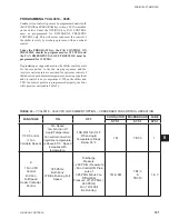
Tables 27 through 30 are a quick reference list providing
the connection points and a description of the inputs and
outputs respectively. All input and output connections
pertain to the connections at the microboard.
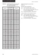
TABLE 27
– I/O DIGITAL INPUTS
J13-2
Unit ON/OFF Switch
J13-3
Load Limit Stage 2 on 3, 5 & 6 Comp. Units
J13-4
Load Limit Stage 1
J13-5
Flow Switch and Remote Start/Stop
J13-6
Spare
J13-7
Single System Select
(Jumper = Single Sys, No Jumper = Two Sys)
J13-8
CR1
(Sys 1 Motor Protector/High Pressure Cutout)
J13-10
CR2
(Sys 2 Motor Protector/High Pressure Cutout)
J7-10
SYS 1 Suction Transducer
-or-
SYS 1 Low Pressure Switch
J11-12
Unit Type: Chiller = NO Jumper J11-12 to +24 VDC
YCUL Condensing Unit = Jumper J11-12 to +24 VDC
(Do NOT Use)
J7-11
SYS 1 Discharge Pressure Transducer (Optional)
J6-9
Ambient Air Temp. Sensor
J6-7
Leaving Chilled Liquid Temp. Sensor
J6-8
Return Chilled Liquid Temp. Sensor
J9-10
SYS 2 Suction Pressure Transducer
-or-
SYS 2 Low Pressure Switch
J9-11
SYS 2 Discharge Pressure Transducer
(Optional)
J7-12
Unit/SYS 1 Voltage
J9-12
SYS 2 Voltage
J11-11
Remote Temperature Reset
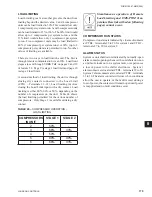
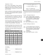
TABLE 28
– I/O DIGITAL OUTPUTS
TB7-2
SYS 1 Compressor 1
TB7-3
SYS 1 Liquid Line Solenoid Valve
TB7-4
SYS 1 Compressor 2
TB7-5
SYS 1 Compressor 3
TB7-7
SYS 1 Hot Gas Bypass Valve
TB10-2
SYS 2 Compressor 1
TB10-3
SYS 2 Liquid Line Solenoid Valve
TB10-4
SYS 2 Compressor 2
TB10-5
SYS 2 Compressor 3
TB7-8
SYS 1 Condenser Fan Output 1
TB7-9
SYS 1 Condenser Fan Output 2
TB7-10
SYS 1 Condenser Fan Output 3
TB10-8
SYS 2 Condenser Fan Output 1
TB10-9
SYS 2 Condenser Fan Output 2
TB10-10
SYS 2 Condenser Fan Output 3
TB8-2
Evaporator Heater
TB8-3
SYS 1 Alarm
TB9-2
SYS 2 Alarm
TB8-6 & 7
Evaporator Pump Starter
TB10-7
SYS 2 Hot Gas Bypass Valve
N/A
Not Applicable
Summary of Contents for YCAL0019
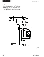
Page 55: ...FORM 150 67 NM2 209 55 JOHNSON CONTROLS 5 5 ELEMENTARY WIRING DIAGRAM CON T LD12699D...
Page 57: ...FORM 150 67 NM2 209 57 JOHNSON CONTROLS 5 5 ELEMENTARY WIRING DIAGRAM CON T LD12693C...
Page 59: ...FORM 150 67 NM2 209 59 JOHNSON CONTROLS 5 5 ELEMENTARY WIRING DIAGRAM CON T LD 12198...
Page 61: ...FORM 150 67 NM2 209 61 JOHNSON CONTROLS 5 5 LD12702 ELEMENTARY WIRING DIAGRAM CON T...
Page 63: ...FORM 150 67 NM2 209 63 JOHNSON CONTROLS 5 5 LD12696 ELEMENTARY WIRING DIAGRAM CON T...
Page 65: ...FORM 150 67 NM2 209 65 JOHNSON CONTROLS 5 5 CONNECTION WIRING DIAGRAM CON T LD12703B...
Page 67: ...FORM 150 67 NM2 209 67 JOHNSON CONTROLS 5 5 CONNECTION WIRING DIAGRAM CON T LD12697B...