


FORM 150.67-NM2 (209)
147
JOHNSON CONTROLS
7
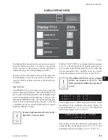
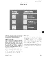
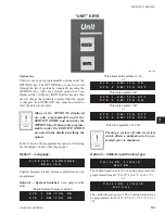
PROGRAM KEY
There are several operating parameters under the
PROGRAM key that are programmable. These setpoints
can be changed by pressing the PROGRAM key, and
then the ENTER/ADV key to enter
Program Mode
.
Continuing to press the ENTER/ADV key will display
each operating parameter. While a particular parameter
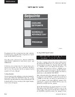
is being displayed, the
↑
(UP) and
↓
(DOWN) arrow
keys can be used to change the value. After the value is
changed, the ENTER/ADV key must be pressed to enter
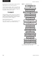
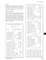
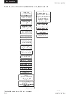
the data into memory. Table 13 shows the programmable
limits and default values for each operating parameter.
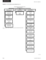
Following are the displays for the programmable values
in the order they appear:
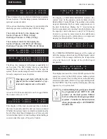
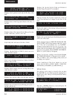
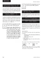
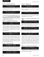
DISCHARGE PRESSURE CUTOUT is the discharge
pressure at which the system will shutdown as monitored
by the
optional
discharge transducer. This is a software
shutdown that acts as a backup for the mechanical high
pressure switch located in the refrigerant circuit. The
system can restart when the discharge pressure drops
40 PSIG (2.76 barg) below the cutout point.
If the optional discharge pressure transducer is not
installed, this programmable safety would not apply.
It should be noted that every system has a
mechanical
high pressure cutout that protects against excessive
high discharge pressure regardless of whether or not the
optional discharge pressure is installed.
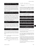
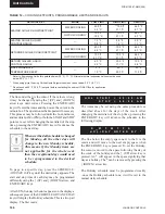
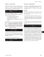
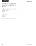
The SUCTION PRESSURE CUTOUT protects the
chiller from an evaporator freeze-up. If the suction
pressure drops below the cutout point, the system will
shut down. Typically, the cutout should be set to 80 PSIG
(5.52 Bars) form water cooling.
There are some exceptions when the
suction pressure is permitted to tem-
porarily drop below the cutout point.
Details are explained under the topic
of SYSTEM SAFETIES.
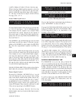
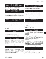
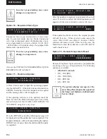
The LOW AMBIENT TEMP CUTOUT allows the user
to select the chiller outside ambient temperature cutout
point. If the ambient falls below this point, the chiller
will shut down. Restart can occur when temperature rises
2 °F (1.11 °C) above the cutout setpoint.
The LEAVING LIQUID TEMP CUTOUT protects
the chiller from an evaporator freeze-up. Anytime the
leaving chilled liquid temperature drops to the cutout
point, the chiller shuts down. Restart will be permitted
when the leaving chilled liquid temperature rises 2 °F
(1.11 °C) above the cutout setpoint.
When water cooling mode is programmed (OPTIONS
key), the value is
fi
xed at 36.0 °F (2.22 °C) and cannot
be changed. Glycol cooling mode can be programmed
to values listed in Table 13.
The programmable anti-recycle timer assures that
systems do not short cycle, and the compressor motors
have sufficient time to dissipate heat after a start.
This timer is programmable under the PROGRAM
key between 300 – 600 seconds. Whenever possible,
to reduce cycling and motor heating, the anti-recycle
timer should be adjusted as high as possible. The
programmable anti-recycle timer starts the timer when
the
fi
rst compressor in a system starts. The timer begins
to count down. If all the compressors in the circuit cycle
off, a compressor within the circuit will not be permitted
to start until the anti-recycle timer has timed out. If the
lead system has run for less than 5 minutes, 3 times
in a row, the anti-recycle timer will be extended to 10
minutes, if currently programmed for < 10 minutes.
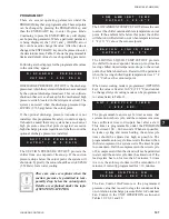
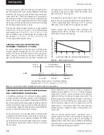
The Fan Control On-Pressure is the programmed
pressure value that is used to stage the condenser fans
on, in relation to discharge pressure. Refer to Condenser
Fan Control in the UNIT OPERATION section and
Tables 19, 20, 21 and 22.
L O W A M B I E N T T E M P
C
U
T
O
U
T = 2
5 . 0
°
F
L E A V I N G L I Q U I D T E M P
C U T O U T = 3 6 . 0 ° F
S U C T I O N P R E S S U R E
C U T O U T = 80 . 0 P S I G
A N T I R E C Y C L E T I M E R
= 6
0
0 S
E
C
F A N C O N T R O L O N
P R E S S U R E
= X X X P S I G
d
D I S C H A R G E P R E S S U R E
C U T O U T = 3 9 5 P S I G
Summary of Contents for YCAL0019
Page 55: ...FORM 150 67 NM2 209 55 JOHNSON CONTROLS 5 5 ELEMENTARY WIRING DIAGRAM CON T LD12699D...
Page 57: ...FORM 150 67 NM2 209 57 JOHNSON CONTROLS 5 5 ELEMENTARY WIRING DIAGRAM CON T LD12693C...
Page 59: ...FORM 150 67 NM2 209 59 JOHNSON CONTROLS 5 5 ELEMENTARY WIRING DIAGRAM CON T LD 12198...
Page 61: ...FORM 150 67 NM2 209 61 JOHNSON CONTROLS 5 5 LD12702 ELEMENTARY WIRING DIAGRAM CON T...
Page 63: ...FORM 150 67 NM2 209 63 JOHNSON CONTROLS 5 5 LD12696 ELEMENTARY WIRING DIAGRAM CON T...
Page 65: ...FORM 150 67 NM2 209 65 JOHNSON CONTROLS 5 5 CONNECTION WIRING DIAGRAM CON T LD12703B...
Page 67: ...FORM 150 67 NM2 209 67 JOHNSON CONTROLS 5 5 CONNECTION WIRING DIAGRAM CON T LD12697B...