


FORM 150.67-NM2 (209)
151
JOHNSON CONTROLS
7
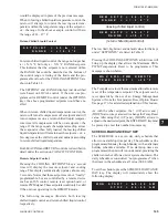
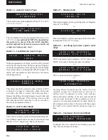
This allows both systems to run
or
This turns system 2 off
This turns system 1 off
or
This turns systems 1 & 2 off
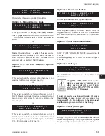
Turning a system off with its system
switch allows a pumpdown to be per-
formed prior to shutdown.
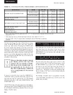
Option 3 – Chilled Liquid Cooling Type:
The chilled liquid is water. The Cooling Setpoint can be
programmed from 40 °F to 70 °F (4.4 °C to 21.1 °C)
or
The chilled liquid is glycol. The Cooling Setpoint can
be programmed from 10 °F to 70 °F (-12.2 °C to 21.1
°C).
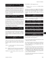
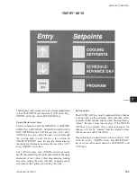
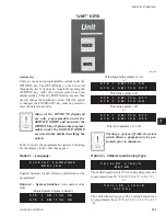
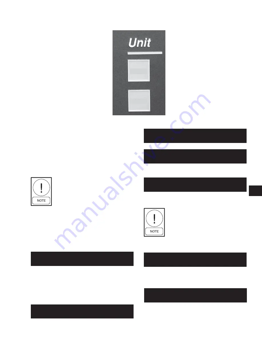
“UNIT” KEYS
Options Key
There are many user programmable options under the
OPTIONS key. The OPTIONS key is used to scroll
through the list of options by repeatedly pressing the
OPTIONS key. After the selected option has been
displayed, the
↑
(UP) and
↓
(DOWN) arrow keys are then
used to change that particular option. After the option
is changed, the ENTER/ADV key must be pressed to
enter the data into memory.
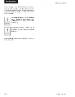
Many of the OPTIONS displayed
are only programmable under the
SERVICE MODE and not under the
OPTIONS key. Options only program-
mable under the SERVICE MODE
are noted in the details describing the
option.
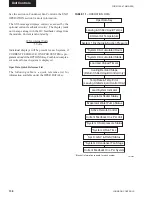
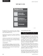
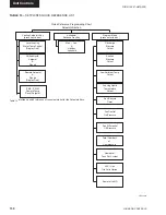
Table 15 shows the programmable options. Following
are the displays in the order they appear:
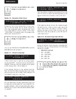
Option 1 – Language:
English, Spanish, French, German, and Italian can be
programmed.
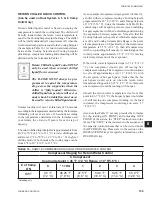
Option 2 – System Switches:
(two system units
only)
(Single System Display is similar)
D I S P L A Y L A N G U A G E
E
N
G
L I
S
H
00070VIP
S Y S 1 S
W I T C H O N
S Y S 2 S
W I T C H O N
S Y S 1 S
W I T C H O N
S Y S 2 S
W I T C H O F F
S Y S 1 S W I T C H O F F
S Y S 2 S
W I T C H O N
S Y S 1 S W I T C H O F F
S Y S 2 S
W I T C H O F F
C H I L L E D L I Q U I D
G L Y C O L
C H I L L E D L I Q U I D
W
A
T
E
R
OPTIONS
OPTIONS
CLOCK
CLOCK
Summary of Contents for YCAL0019
Page 55: ...FORM 150 67 NM2 209 55 JOHNSON CONTROLS 5 5 ELEMENTARY WIRING DIAGRAM CON T LD12699D...
Page 57: ...FORM 150 67 NM2 209 57 JOHNSON CONTROLS 5 5 ELEMENTARY WIRING DIAGRAM CON T LD12693C...
Page 59: ...FORM 150 67 NM2 209 59 JOHNSON CONTROLS 5 5 ELEMENTARY WIRING DIAGRAM CON T LD 12198...
Page 61: ...FORM 150 67 NM2 209 61 JOHNSON CONTROLS 5 5 LD12702 ELEMENTARY WIRING DIAGRAM CON T...
Page 63: ...FORM 150 67 NM2 209 63 JOHNSON CONTROLS 5 5 LD12696 ELEMENTARY WIRING DIAGRAM CON T...
Page 65: ...FORM 150 67 NM2 209 65 JOHNSON CONTROLS 5 5 CONNECTION WIRING DIAGRAM CON T LD12703B...
Page 67: ...FORM 150 67 NM2 209 67 JOHNSON CONTROLS 5 5 CONNECTION WIRING DIAGRAM CON T LD12697B...